Unity Shader 基础篇
计算机图形学第一定律: 如果它看起来是对的,那么它就是对的。
unity项目地址:https://github.com/IceMiaoMiao/Unity-Shader-Study-Projects
Shader
1.渲染流水线
工作任务:
由一个三维场景出发、 生成(或者说渲染) 一 张二维图像。换句话说, 计算机需要从一 系列的顶点数据、纹理等信息出发,把这些信息最终转换成 一 张图像。
渲染流程的三个阶段:
应用阶段(Application Stage)、 几何阶段(Geometry Stage)、 光栅化阶段(Rasterizer Stage)。
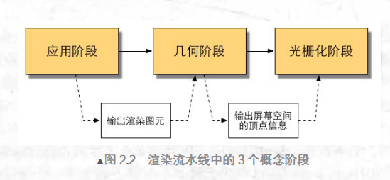
应用阶段:
是由应用主导的, 因此通常由CPU负责实现。开发者有三个任务:准备场景数据、粗粒度剔除、设置模型的渲染状态。
这一阶段最重要的任务是输出渲染图元,传递给下一阶段(几何阶段)。
几何阶段:
用于处理所有和我们要绘制的几何相关的事情。例如,决定需要绘制的图元是什么,怎样绘制它们,在哪里绘制它们。这一阶段通常在 GPU 上进行 。 几何阶段负责和每个渲染图元打交道,进行逐顶点、逐多边形的操作。
这一阶段最重要的任务是把顶点坐标变换到屏幕空间中。然后进行光栅化,绘制到屏幕上。这一阶段会输出屏幕空间的二维顶点坐标,每个顶点的深度值,着色等相关信息,并传递到下一阶段(光栅化阶段)。
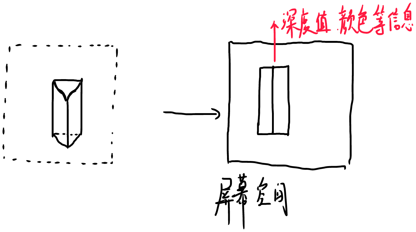
光栅化阶段
产生像素,绘制图像。
2. CPU与GPU的通信
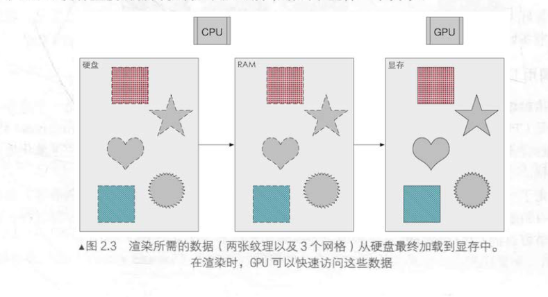
硬盘,内存与显存
从硬盘中读取数据,加载到内存上,显存直接从系统内存中访问数据。
设置渲染状态
什么是渲染状态呢?
定义了场景中的网格是怎样被渲染的。
例如, 使用哪个顶点着色器 (Vertex Shader) /片元着色器 (Fragment Shader)、 光源属性、材质等。
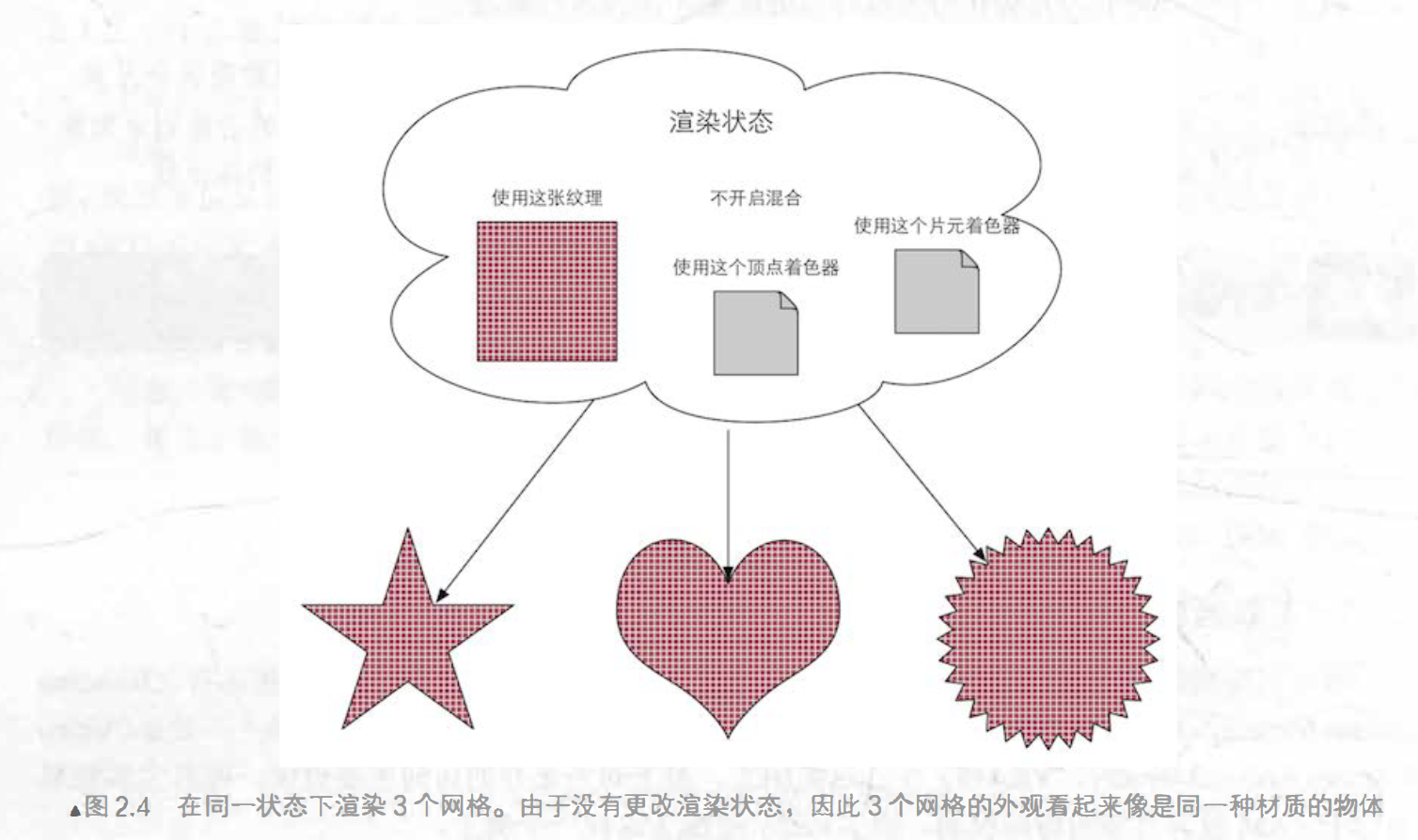
Draw Call
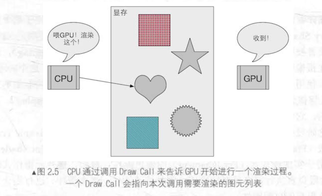
draw call 就是一个命令,他是CPU发起的,GPU接收的。
定义一个draw call后,GPU就会根据渲染状态来计算,并绘制出屏幕上的像素。
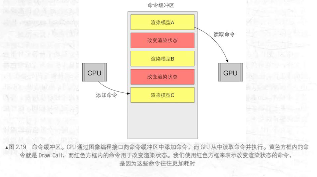
命令缓冲区:
命令缓冲区可以让CPU与GPU实现并行工作,其包含了一个命令队列 CPU 向其中添加命令 , GP U 从中读取命令。
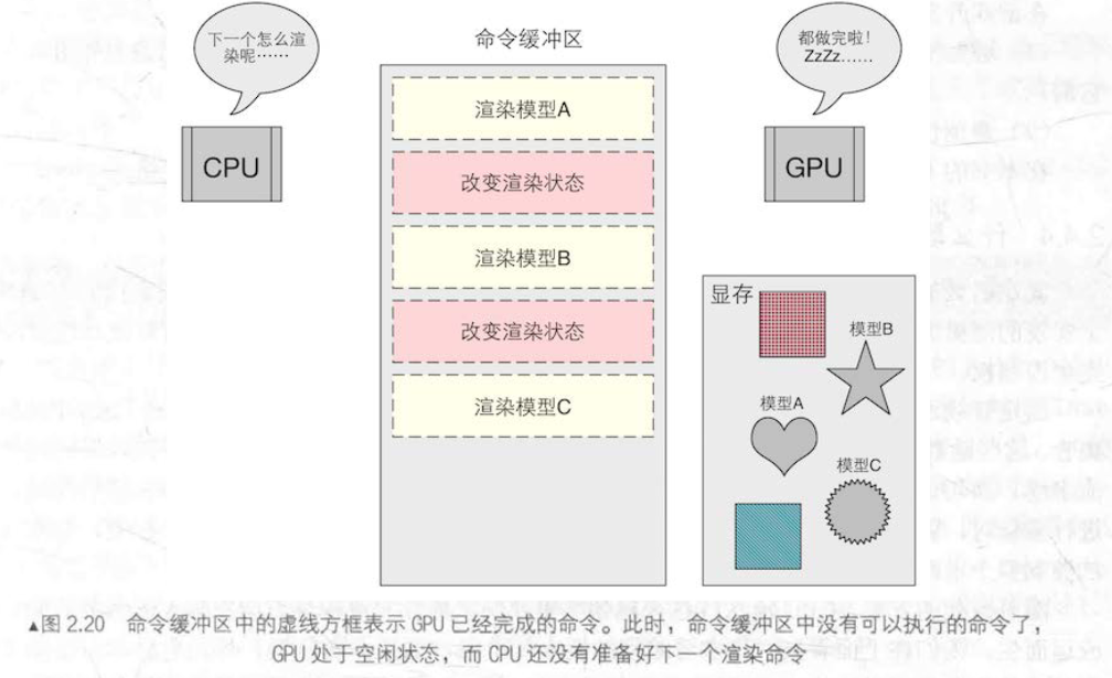
为什么Draw Call 多了会影响帧率?
在每次调用 Draw Call 之前, CPU 需要向 GPU 发送很多内容,包括数据、状态和命令等。在这一阶段, CPU 需要完成很多工作,例如检查渲染状态等。而GPU处理这些渲染很快,渲染速度取决于CPU提交命令的速度。
批处理(减少draw call)
适合静态的物体,把一些小的draw call合并成一个大draw call.
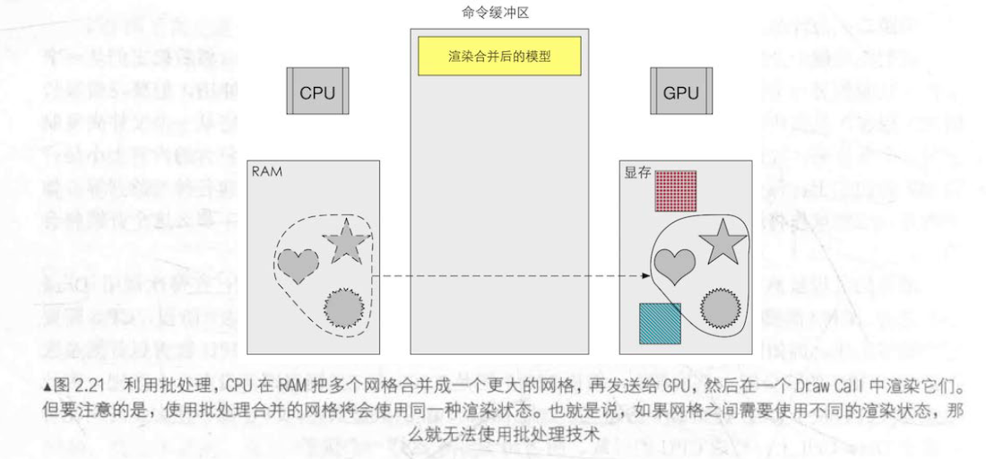
其他办法:
(1) 避免使用大量很 小的网格 。当不可避免地需要使用很小的网格结构时,考虑是否可以合并它们 。
(2) 避免使用过多的材质。尽量在不同的网格之间共用同一个材质。
3. GPU 的流水线
GPU渲染的过程就是GPU流水线,通过流水线,可以大大加快渲染速度。
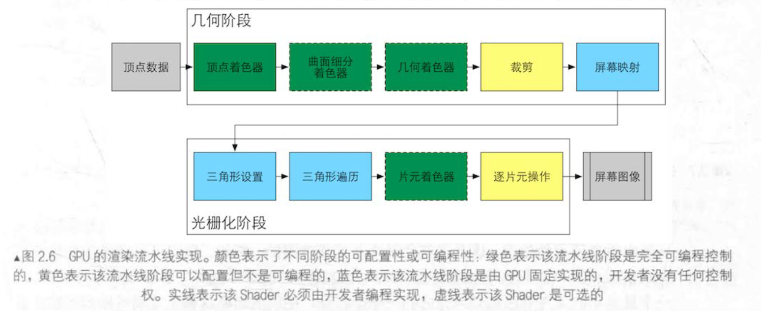
过程介绍
GPU流水线从接收显存中的顶点数据开始。
随后是顶点着色器:
顶点着色器 (Vertex Shader) 是完全可编程的,它通常用千实现顶点的空间变换 、 顶点着色等功能。
曲面细分着色器 (Tessellation Shader) 是一个可选的着色器,它用于细分图元。
几何着色器 (Geometry Shader) 同样 是一个可选的着色器,它可以被用于执行逐图元 ( Pre-Primitive )的着色操作,或者被用于产生更多的图元。
下 一个流水线阶段是裁剪 (Clipping), 这一阶段的目的是将那些不在摄像机视野内的顶点裁剪掉,并剔除某些三角图元的面片。
顶点着色器
主要工作是:坐标变换和逐顶点光照,输出后续阶段所需要的数据。
输入进来的每一个顶点都会调用顶点着色器,其处理顶点具有独立性,大大加快了处理速度。
但其本身不创造和销毁顶点,也无法得到顶点之间的关系。(例如不能判断三个顶点是否属于同一个三角形)
坐标变换
就是对顶点的坐标(即位置)进行某种变换。顶点着色器可以在这一步中改变顶点的位置,这在顶点动画中是非常有用的。
其最基本的工作是:把顶点坐标从模型空间转换到齐次裁剪空间。
因此我们经常在顶点着色器中看到:
o.pos = mul(UNITY_MVP, v.position);类似上面这句代码的功能,就是把顶点坐标转换到齐次裁剪坐标系下接着通常再由硬件做透视除法后,最终得到归一化的设备坐标 (Normalized Device Coordinates , NDC )。
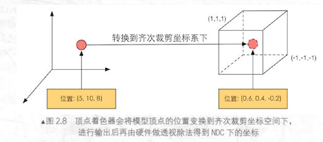
需要注意的是 ,图 2.8 给出的坐标范围是 OpenGL 同时也是 Unity 使用的 NDC, 它的 z 分量范围在 [-1 , l] 之间,而在 DirectX 中, NDC 的 z 分量范围是 [ 0, 1] (1)
顶点着色器输出可以有很多种,最常见的输出路径是经光栅化后交给片元着色器进行处理,或者把数据发送给曲面细分着色器或几何着色器。
裁剪
一 个图元和摄像机视野的关系有 3 种 : 完全在视野内、部分在视野内、完全在视野外。
完全在视野内的图元就继续传递给下一个流水线阶段.
完全在视野外的图元不会继续向下传递 ,因为它们不需要被渲染。
而那些部分在视野内的图元需要进行一个处理,这就是裁剪。例如 ,一条线段的一个顶点在视野内 ,而另 一个顶点不在视野内,那么在视野外部的顶点应该使用一个新的顶点来代替,这个新的顶点位于这条线段和视野边界的交点处。

屏幕映射
这一步的输入坐标仍然是三维坐标系下的坐标,屏幕映射的主要任务是把每个图元和x,y坐标转换到屏幕坐标系下,这是一个二维坐标系,大小取决于我们的屏幕。
如果输入的 z 坐标会怎么样呢?
屏幕映射不会对输入的 z 坐标做任何处理。实际上,屏幕坐标系和 z 坐标 一 起构成了 一 个坐标系,叫做窗口坐标系 (Window Coordinates) 。这些值会一起被传递到光栅 化阶段 。
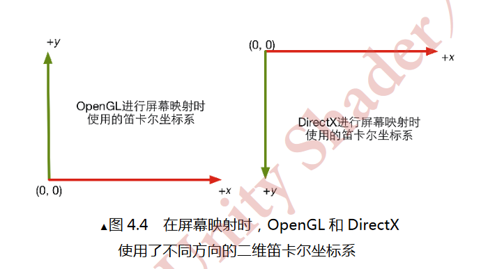
我们仍需要在这一步中注意OpenGL和DirectX中的差异问题,OpenGL把屏幕的左下角当成最小的窗口坐标值,而 DirectX 则定义了屏幕的左上角为最小的窗口坐标值。(2)

光栅化阶段:
1.三角形设置
这个阶段会计算光栅化一个三角网格所需的信息。具体来说,上一个阶段输出的都是三角网格的顶点,即我们得到的是三角网格每条边的两个端点。但如果要得到整个三角网格对像素的覆盖情况 , 我们就必须计算每条边上的像素坐标。为了能够计算边界像素的坐标信息,我们就需要得到三角形边界的表示方式 。这样一 个计算三角网格表示数据的过程就叫做三角形设置。它的输出可以给下一阶段做准备。
2.三角形遍历(扫描变换)
检查每个像素是否被三角形网格所覆盖。如果被覆盖的话,就会生成一个 片元(fragment) 。而这样一个找到哪些像素被三角网格覆盖的过程就是三角形遍历,这个阶段也被称为 扫描变换 (Scan Conversion) 。
三角形遍历阶段会根据上 一 个阶段的计算结果来判断一个三角网格覆盖了哪些像素,并使用三 角网格 3 个顶点的顶点信息对整个覆盖区域的像素进行插值。
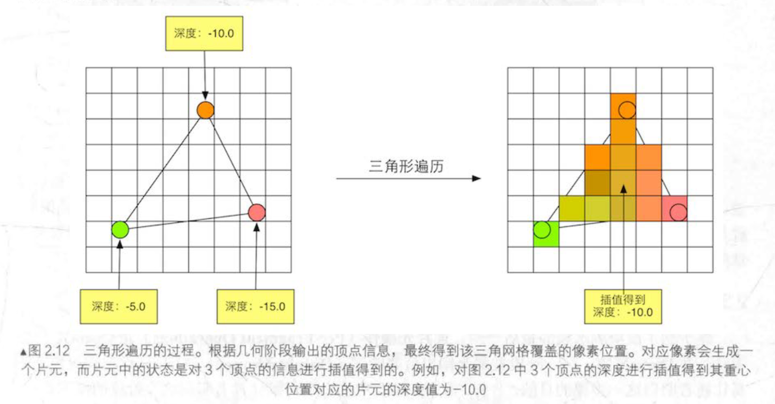
这一步的输出就是得到 一 个片元序列。需要注意的是,一个片元并不是真正意义上的像素 ,而是包含了很多状态的集合 , 这些状态用于计算每个像素的最终颜色。这些状态包括了(但不限于)它的屏幕坐标 、 深度信息,以及其他从几何阶段输出的顶点信息 , 例如法线、纹理坐标等。
3.片元着色器(像素着色器)
前面的光栅化阶段实际上并不会影响屏幕上每个像素的颜色值,而是会产生一系列的数据信息,用来表述一个三角网格是怎样覆盖每个像素的。而每个片元就负责存储这样一系列数据。
片元着色器的输入是上 一个阶段对顶点信息插值得到的结果 , 更具体来说,是根据那些从顶点着色器中输出的数据插值得到的。而它的输出是 一 个或者多个颜色值。
这一阶段可以完成很多重要的渲染技术,其中最重要的技术之一就是纹理采样。为了在片元着色器中进行纹理采样,我 们 通常会在顶点着色器阶段输出每个顶点对应的纹理坐标 , 然后经过光栅化阶段对 三 角网格的 3 个顶点对应的纹理坐标进行插值后,就可以得到其覆盖的片元的纹理坐标了。
4.逐片元操作(输出合并阶段):
主要任务:
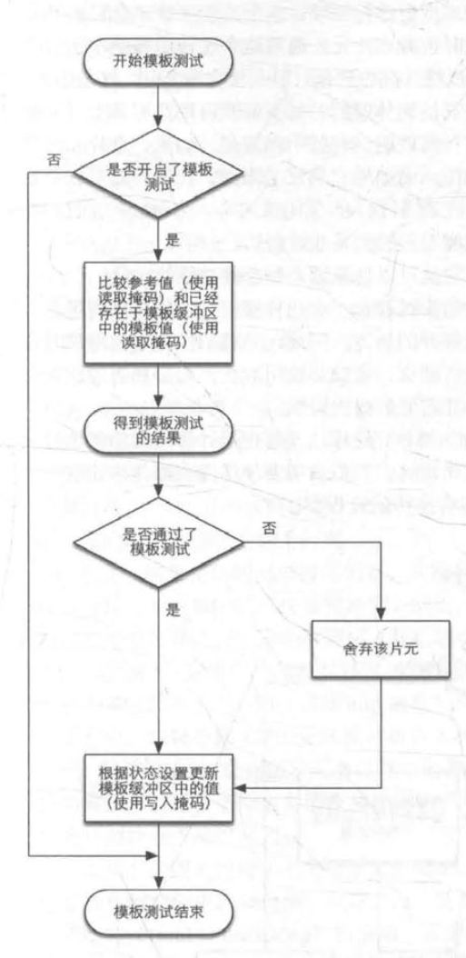
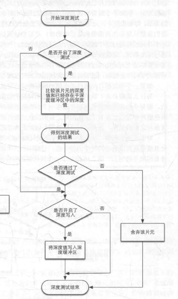
(1) 决定每个片元的可见性。这涉及了很多测试工作,例如深度测试、模板测试等 。
( 2 ) 如果一个片元通过了所有的测试 , 就需要把这个片元的颜色值和已经存储在颜色缓冲区中 的 颜色进行合并 , 或者说是混合。
这个阶段首先需要解决每个片元的可见性问题。一个片元只有通过了所有的测试,才会在颜色缓冲区进行合并。

模板测试
深度测试
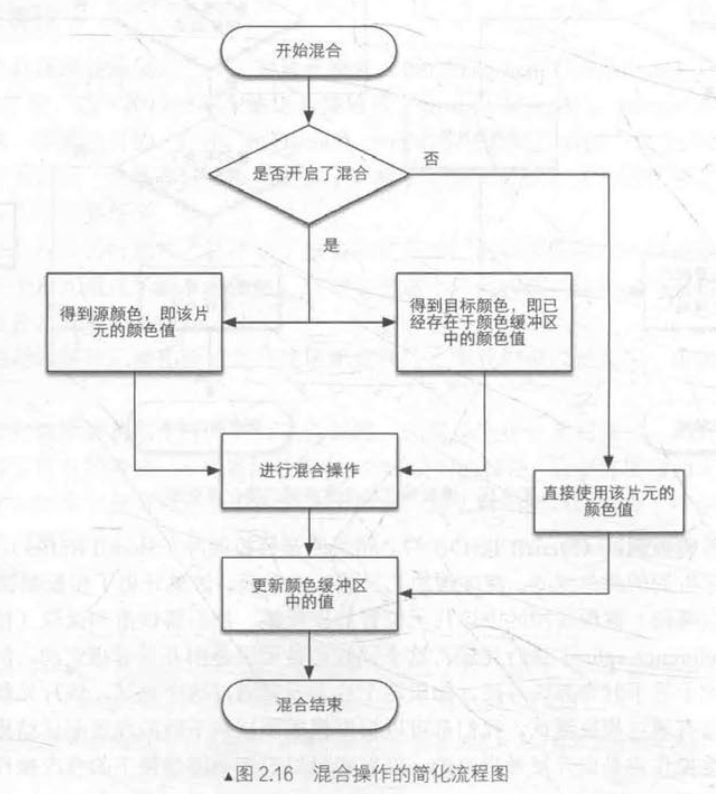
合并
片元成功通过模板测试和深度测试后,即可进行合并的操作
合并:
如果是不透明的,可以覆盖掉颜色缓冲区的像素值。
如果是半透明,我们需要混合操作让这个物体看起来是透明的
如果想提高GPU性能,可以把这些测试放在片元着色器之前做。
但提前测试的话,可能会发生一些冲突,例如透明度测试:如果我们在片元着色器进行了透明度测试,而这个片元没有通过透明度测试,就无法实现透明效果。所以有冲突时,我们需要手动禁用提前测试。
当模型的图元经过了上而层层计算和测试后, 就会显示到我们的屏幕上。 我们的屏幕显示的就是颜色缓冲区中的颜色值。 同时,为了避免看到正在光栅化的图元,GPU会使用双重缓冲(Double Buffering) 的策略。在后置缓冲中渲染场景,前置缓冲显示图像,随后交换前后缓冲,使我们看到的图像总是连续的。
4.拓展
1.什么是OpenGL / DirectX
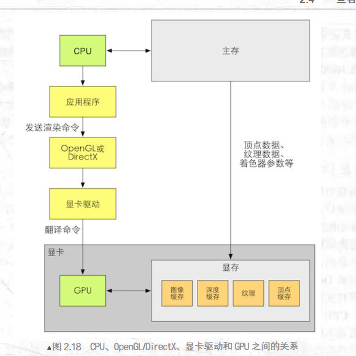
这两者是互为竞争关系的图像编程接口,它是硬件基础上的一层抽象,避免了我们直接访问GPU,和寄存器,显存打交道。
这些接口可以渲染二维和三维图形,是上层应用程序和底层GPU沟通的桥梁。
显卡驱动就是显卡的操作系统,可以把接口的函数调用翻译成GPU能听懂的语言,把纹理坐标转换成GPU支持的格式。
2.什么是HLSL、 GLSL、 CG
这些是更高级的着色语言(shading language),包含了DirectX的HLSL (High Level Shading Language)、 OpenGL的GLSL(OpenGL Shading Language)以及NVIDIA的CG (C for Graphic)。
GLSL:
优点:跨平台(indows、Linux、 Mac以及移动平台),依赖硬件。
HLSL:
仅仅支持微软平台
CG:
优点:真正的跨平台,与HLSL类似
缺点:无法发挥OpenGL的最新特性。
什么是shader
• GPU 流水线上一些可高度编程的阶段,而由着色器编译出来的最终代码是会在 GPU 上运行的(对于固定管线的渲染来说,着色器有时等同于一些特定的渲染设置);
• 有一 些特定类型的着色器,如顶点着色器、片元着色器等;
• 依靠着色器我们可以控制流水线中的渲染细节,例如用顶点着色器来进行顶点变换以及传递数据,用片元着色器来进行逐像素的渲染。
Unity Shader
类型:
1.Standard Surface Shader:包含标准光照模型
2.Unlit Shader:不包含光照(但包含雾效)的基本的顶点/片元着色器
3.Image Effect Shade:提供屏幕后处理效果的基本模板
4.Compute Shader:利用GPU的并行性来进行一些与常规渲染流水线无关的计算
ShaderLab
ShaderLab的结构
1.名字
2.属性(Properties)
声明属性可以方便我们调整各种材质的属性。
属性语义的定义:
Properties {
	Name (" display name" , PropertyType) = DefaultValue
	Name ("display name", PropertyType) = DefaultValue
	//更多属性
}
Name是每个属性的名字,通常以下划线开始
display name 是出现在材质面板上的名字
PropertyType是类型
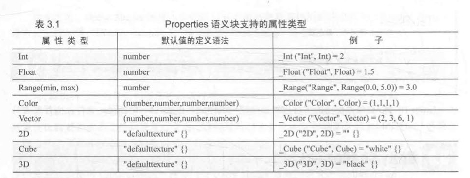
2D 、 Cube 、 3D 这 3 种纹理类型,它们的默认值是通过一个字符串后跟一个花括号来指定的,其中,字符串可以是空的或者内置的纹理名称,如 “white” “black” “gray” 或者 “bump” .
SubShader
SubShader语义块中包含的定义通常如下;
SubShader {
//可选的
[Tags]
//可选的
[RenderSetup)
Pass {
}
// Other Passes
}
SubShader中定义了一系列的Pass以及可选的Tags[Tags]和状态[RenderSetup]
1.渲染状态
可以设置显卡的各种状态,例如是否开启混合/深度测试等。(也可以放在Pass语义块中)

2.标签
SubShader的标签(Tags)是 一 个键值对(Key/Value Pair), 它的键和值都是字符串类型。
Tags { " TagNamel " = " Valuel " " TagName2" = " Value2 " }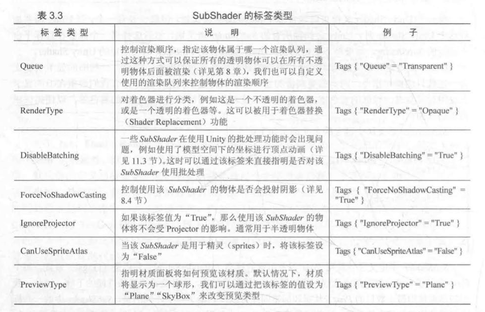
3.Pass语义块
Pass{
	[name]
	[tags]
	[RenderSetup]
}
定义名称
Name "MyPassName "通过名称可以调用其他pass
Use Pass " MyShader /MYPASSNAME "注意,使用UsePass时必须用大写的名字。
Pass里面也可以设置标签,但不同于SubShader
| 标签类型 | 说明 | 例子 |
|---|---|---|
| LightMode | 定义该 Pass 在 Un ity 的 渲染流水线中的角色 | Tags { “LightMode” = “ForwardBase” } |
| RequireOptions | 用于指定当满足某些条件时才渲染该 Pass, | Tags { “RequireOptions” = “SoftVegetation” } |
特殊Pass:
GrabPass:抓取屏幕存储在一张纹理中。
4.FallBack
Fallback "name"
or
Fallback off
就是说,以上subshader都无法执行的话,就执行fallback,相当于留一条后路
SubShader的形式
Shader "MyShader " {
Properties {
	//所需的各种属性
}
SubShader {
//真正意义上的 Shader 代码会出现在这里
//表面着色器 (Surface Shader) 或者
//顶点/片元着色器 (Vertex/Fragment Shader) 或者
//固定函数着色器 (Fixed Function Shader)
}
SubShader {
//和上—个 SubShader 类似
}
}
表面着色器
是对于顶点/片元着色器的抽象,Unity在其中为我们处理了很多光照细节,需要注意的是,表面着色器定义在SubShader中,而非Pass。
一个简单的表面着色器的例子:
Shader "Custom/Simple Surface Shader" {
SubShader {
	Tags ( " RenderType " = " Opaque" }
	CGPROGRAM
	#pragma surface surf Lambert
	struct Input{
	float4 color : COLOR ;
	};
	void surf (Input IN, inout SurfaceOutput o) {
	o.Albedo = l;
	}
	ENDCG
	Fallback "Diffuse "
}
顶点/片元着色器(Vertex/Fragment Shader)
顶点/片元着色器需要写在Pass中,非常灵活,但也更加复杂
例子:
Shader "Custom/Simple VertexFragment Shader" {
SubShader {
	Tags ( " RenderType " = " Opaque" }
	CGPROGRAM
	#pragma vertex vert
	#pragma fragment frag
	struct vert(float4 v:POSITION):SV_POSITION
	{
		return mul (UNITY_MATRIX_MVP, v);

	};//注意,结构体后面有冒号
	void frag():SV_POSITION
	{
		return fixed4 (1.0, 0.0, 0.0, 1.0);
	}

	ENDCG
	Fallback "Diffuse "
}
}
官方文档
Unity Shader文档:http://docs.unity3d.com/Manual/SL-Reference.html
着色器编写教程:http://docs.unity3d.com/Manual/ShaderTut1.html
http://docs.unity3d.com/Manual/ShaderTut2.html
NVIDNA的CG文档:http://http.developer.nvidia.com/CG/
http://http.developer.nvidia.com/CGTutorial/cg_tutorial_chapter01.html
数学基础
坐标系(Unity是左手坐标系)
二维:
OpenGL和DirectX使用了不同的二维坐标系(3)
三维:
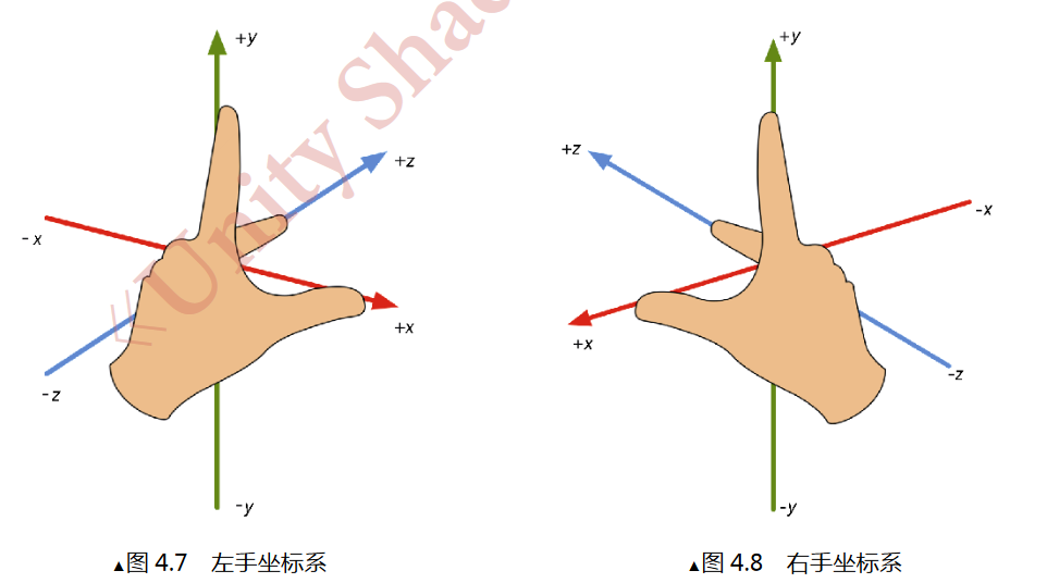
三维坐标系也有两种:左手坐标系和右手坐标系
为什么要这样区分呢?
和二维不同,二维坐标系都是等价的,而三维坐标系中左手系和右手系中只靠旋转,并不能完全重合。
如何判断左手系和右手系:
拇指(x)和中指(z)成90°,水平方向,食指(y)朝上,此时便得到了左手系。
旋转
以左手坐标系为例
左手握拳,拇指指向旋转轴的正方向,四指弯曲的方向即为旋转的正方向
矩阵的变换
线性变换
缩放,旋转
满足条件
$$
f(x)+f(y)=f(x+y)
$$
$$
kf(x)=f(kx)
$$
仿射变换、
解决了3x3矩阵不能表示平移变换的问题(平移变换不是线性变换,因为它不满足标量法和矢量加法)。
仿射变换可以用4x4的矩阵表示,它合并了线性变换和平移变换。
我们把矢量扩展到四维空间后,这个空间就变成了齐次坐标空间。
分解基础变换矩阵
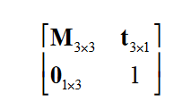
M表示旋转和缩放,t表示平移
平移矩阵
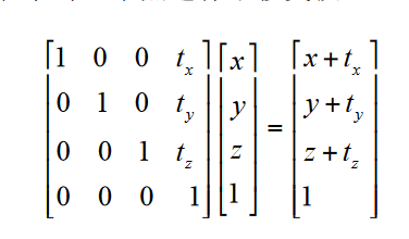
平移矩阵不是正交矩阵
缩放矩阵
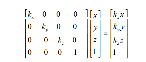
缩放矩阵一般不是正交矩阵
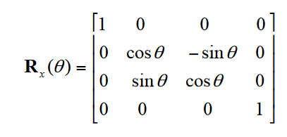
旋转矩阵
围绕哪个轴旋转,对应位置就是1
围绕x轴
y轴
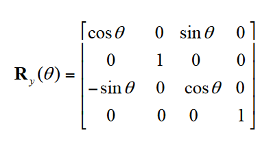
z轴
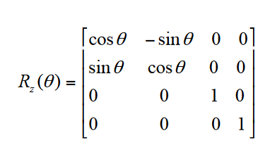
复合变换
就是把平移,旋转,缩放矩阵组合
$$
P_n = M_tM_rM_sP_o
$$
阅读的顺序,是从右往左,也就是说,变换的顺序,是先缩放,再旋转,最后平移
那么如果有多个方向的角度,旋转的顺序是什么呢?
在Unity中,这个旋转顺序是zxy

坐标空间
模型空间
是一个顶点初始状态所在的空间,它和对象(或者说是物体有关),也可以叫做对象空间或者局部空间。
世界空间
第一步就是把顶点从模型空间变换到世界空间中,
$$
P_w = M_mP_m
$$
w = world, m = model
$$
求M_m的办法就是,依据父节点的复合变换矩阵(先缩放,再旋转,最后平移)
$$
观察空间
第二步就是把顶点从世界空间变换到观察空间
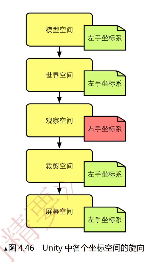
Unity中观察空间所使用的是右手坐标系(x轴指向右,y轴向上,z轴向后),这一点与其他空间不同
$$
P_v = M_vP_w
$$
$$
M_v的求法是:通过复合变换,把摄像机移动到原点的矩阵,然后对z轴取反
$$
裁剪空间(齐次裁剪空间)
第三步是把顶点从观察空间转到裁剪空间中,用于这一步变换的矩阵是裁剪矩阵(或者是投影矩阵)
裁剪空间由视锥体(由六个平面包围而成)决定,决定了摄像机能够看到的空间,视锥体有两种类型:正交投影和透视投影
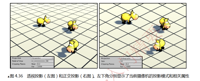
透视投影模拟了人眼看世界的方式,正交投影保留了物体的距离和角度。
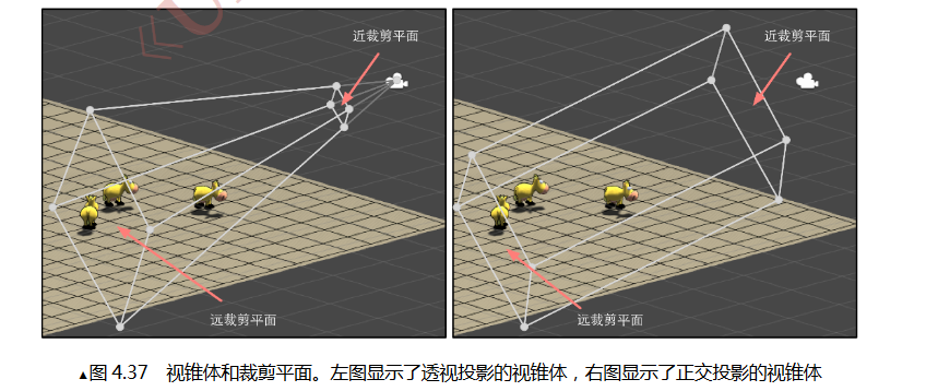
对于透视投影来说,想要判断一个顶点是否处于金字塔内部比较麻烦,因此,我们可以用投影矩阵把顶点转换到一个裁剪空间中。
投影矩阵的目的
- 为投影做准备,实际上投影矩阵并没有真正地进行投影,真正的投影发生在齐次除法中(降维,把三维空间变为二维坐标)
- 对x,y,z分量缩放
透视投影的投影矩阵
这里可以通过控制摄像机的FOV(field of view),来控制视锥体竖直方向的张开角度
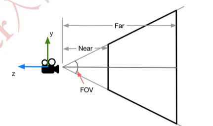
$$
nearClipPlaneHeight = 2 * Near * tan(FOV/2)
$$
$$
farClipPlaneHeight = 2 * Far * tan(FOV/2)
$$
可以求得投影矩阵
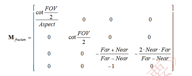
顶点与投影矩阵相乘后,即可由观察空间变换到裁剪空间中
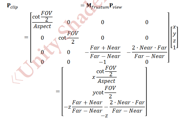
从结果可以看出,投影矩阵的本质就是对x,y,z分量进行不同程度的缩放
只有满足条件的点,才会显示在视锥体中:
$$
-w<=x<=w
$$
$$
-w<=y<=w
$$
$$
-w<=z<=w
$$
经过投影矩阵变换后,视锥体的变化:
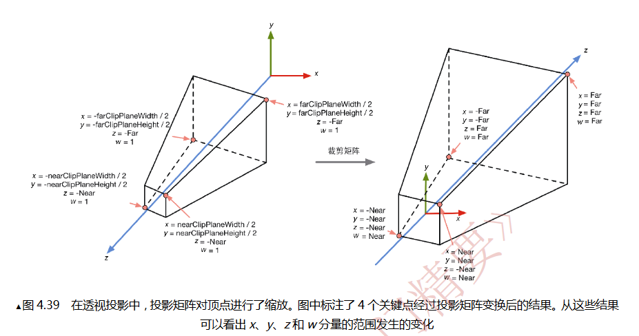
正交投影的投影矩阵
首先确定裁剪矩阵,把视锥体边长裁为1
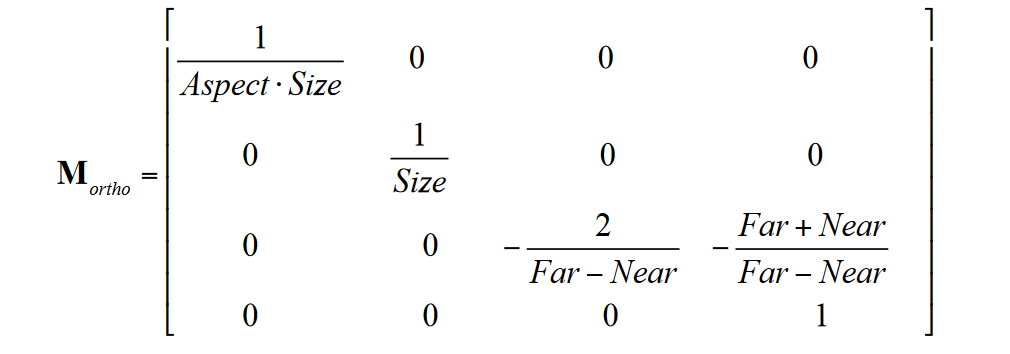
aspect是当前摄像机的横纵比
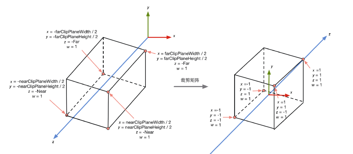
$$
P_c = M_fP_v
$$
c = clip f=frustum v = view
屏幕空间
把视锥体投影到屏幕空间,这一步是真正的投影,经过此变换我们会得到真正的像素位置。
这个过程需要两个步骤:
1.进行标准齐次除法(透视除法),即用齐次坐标系的w分量去除以x,y,z分量。这一步可以得到归一化的设备坐标(NormalizedDevice Coordinates,NDC),此时裁剪空间会变到一个立方体内。
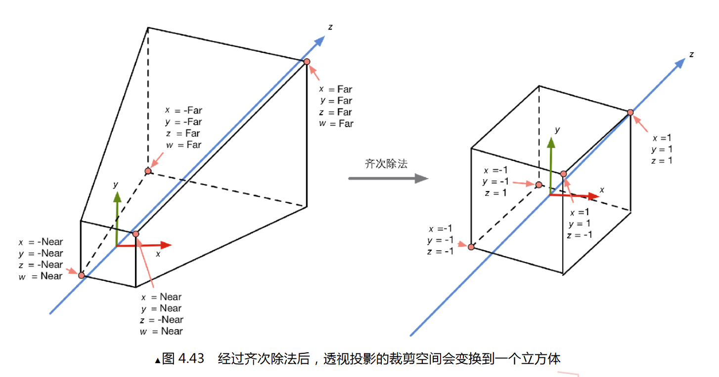
Unity和OpenGL中,这个立方体分量都是[-1,1],而DirectX中,z的分量会变成[0,1]
2.根据变换后的x,y坐标来映射输出窗口的像素坐标。
在Unity中,左下角的像素坐标是(0,0)右上角是(pixelWidth,pixelHeight),由于现在x和y坐标都是[-1,1],因此这个映射过程是一个缩放的过程。
总结
顶点着色器最基本的任务就是把顶点坐标从模型空间转换到裁剪空间中。
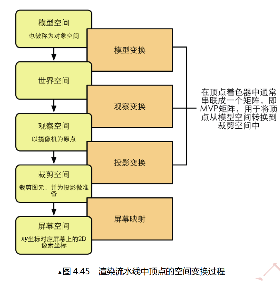
法线变换
法线是顶点隐藏的信息
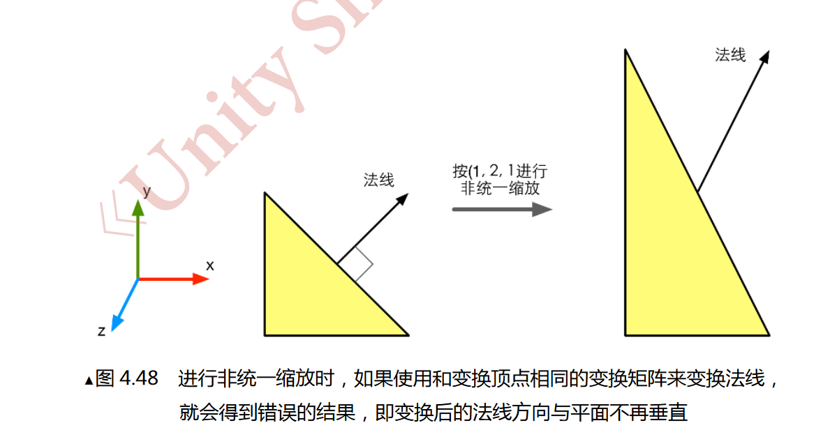
如果对物体进行非统一变换,新法线可能与物体不再垂直了
$$
我们知道,同一个顶点的切线T_A和法线N_A必须满足条件:T_A.N_A=0
$$
$$
对于切线的变换:T_B = M_AT_A
$$
M就是M(A->B)
我们现在需要一个矩阵N,使变换后的法线仍然与切线垂直
$$
T_B.N_B = (M_AT_A).(GN_A)=0
$$
推导后得:

如果

那么上式即可成立,即

$$
如果M_A是正交矩阵,有M_A^-1=M_A^T,因此(M_A^T)_-1=M_A,
$$
此时我们可以用变换顶点的变换矩阵直接变换法线
如果只包含旋转变换,那么变换矩阵就是正交矩阵
如果包含旋转和统一缩放,我们可以用统一缩放系数k来得到变换矩阵的逆转置矩阵

如果包含非统一变换的话,需要求解逆矩阵
内置数学变量
1.变换矩阵
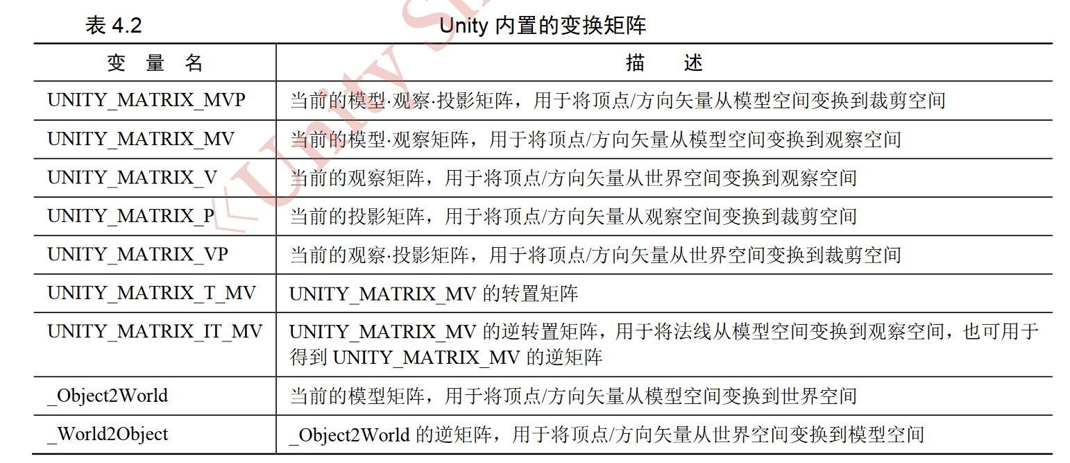
当只包含旋转和统一缩放时,UNITY_MATRIX_MV是正交矩阵,UNITY_MATRIX_MV的逆矩阵UNITY_MATRIX_T_MV可以把顶点/方向矢量从观察空间变换到模型空间。
把顶点/方向矢量从观察空间变换到模型空间的具体代码
//使用tranpose函数对UNITY_MATRIX_IT_MV进行转置,得到逆矩阵后,进行行矩阵乘法
float4 modelPos = mul(transpose(UNITY_MATRIX_IT_MV), viewPos);
//交换mul参数的位置,使用行矩阵乘法
float4 modelPos = mul(viewPos, UNITY_MATRIX_IT_MV)
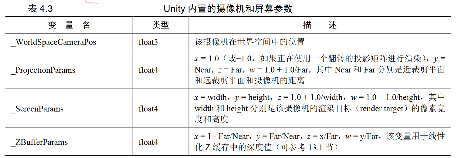
2.摄像机和屏幕参数

Unity初级
如何编写Unity Shader
顶点/片元着色器
Simple Shader
首先来写一个最简单的着色器
// Upgrade NOTE: replaced 'mul(UNITY_MATRIX_MVP,*)' with 'UnityObjectToClipPos(*)'

Shader "Unity Shaders Book/Chapter5/Simple Shader"//定义shader的名字和位置
{
    SubShader
    {
        Pass
        {
            CGPROGRAM
			//由 CGPROGRAM 和 ENDCG 所包围的 CG 代码片段
            #pragma vertex vert
            #pragma fragment frag
			//编译指令,告诉unity哪个函数包含了顶点着色器或者片元着色器的代码

            float4 vert(float4 v:POSITION):SV_POSITION
            {
                return UnityObjectToClipPos(v);

            }
            fixed4 frag():SV_Target
            {
                return fixed4(1.0,1.0,1.0,1.0);
            }

            ENDCG
        }
    }
}
POSITION 和 SV_POSITION 都是 CG/HLSL 中的语义
POSITION指定了v的输入,意为把模型顶点填充到参数v中。POSITION的返回值是一个float4类型的变量,即该顶点在裁剪空间中的位置。
SV_POSITION的语义是:顶点着色器的输出是裁剪空间中的顶点坐标
SV_Target的语义是:告诉渲染器,把输出颜色存储在一个渲染目标中,这里是指默认的帧缓存。

Simple Shader的效果
得到更多模型数据
POSITION语义只能得到模型顶点的位置,如果我们需要获取模型更多数据,可以自己编写结构体输入与输出
例如,访问模型的纹理坐标和法线方向
struct a2v//使用结构体定义顶点着色器的输入
{
                float4 veretx:POSITION;
                //使用POSITION语义,意为用模型空间的顶点坐标填充vertex变量
                float3 normal:NORMAL;
                //使用NORMAL语义,意为用模型空间的法线方向填充normal变量
                float4 texcoord : TEXCOORD0;
                //使用TEXCOORD0语义,意为用模型的第一套纹理坐标填充texcoord变量
};
我们声明的结构体a2v中,使用了更多语义来得到模型的更多细节。a2f(a:application,v:vertex shader)意思就是把数据从应用阶段传递到顶点着色器中。
顶点着色器与片元着色器之间的通信
通过通信,可以把顶点着色器输出的一些数据(模型的法线,纹理坐标)传递给片元着色器。
实现通信的话,需要定义一个新的结构体
Shader "Unity Shaders Book/Chapter 5/Simple Shader" {
	SubShader {
		Pass {
			CGPROGRAM
			#pragma vertex vert
			#pragma fragment frag
			struct a2v {
			float4 vertex : POSITION;
			float3 normal: NORMAL;
			float4 texcoord: TEXCOORDO;
			//使用一个结构体来定义顶点着色器的输出
			};
			struct v2f {
			// SV_POSITION语义告诉Unity, pos里包含了顶点在裁剪空间中的位置信息
			float4 pos : SV POSITION;
			// COLORO语义可以用于存储颜色信息
			fixed3 color: COLORO;
			};
			v2f vert(a2v v) {
			//v2f在这里意思是:向片元着色器中输出数据
			v2f o;//声明输出结构
			o.pos = mul(UNITY MATRIX MVP, v.vertex);
			// v.normal包含了顶点的法线方向,其分量范围在[-1.0, 1.0]
			//下面的代码把分量范围映射到了[0.0, 1.0]
			//存储到o.color中传递给片元着色器
			a.color= v.normal * 0.5 + fixed3(0.5, 0.5, 0.5);
			return o;
			};
			fixed4 frag(v2f i) : SV Target //这里v2f是接受顶点着色器传来的数据
			{
			//将插值后的i.color显示到屏幕上
			return fixed4(i.color, 1.0);
			};
			ENDCG
		}
    }
}
v2f中也需要指定每个变量的语义,用于在顶点着色器和片元着色器之间传递信息。顶点着色器是逐顶点调用的,而片元着色器是逐片元调用的。 片元着色器中的输入实际上是把顶点着色器的输出进行插值后得到的结果。
如何使用属性
属性在材质面板中会变成参数,这些参数需要写在Properties语义块中
Properties {
	//声明 一 个Color类型的属性
	_Color ("Color Tint", Color) = (l.O,l.O,l.0,1.0)
	Name (" display name" , PropertyType) = DefaultValue
}

...
fixed 4 _Color;
//在CG代码中定义一个与属性类型和名称都匹配的变量

...
Name是每个属性的名字,通常以下划线开始
display name 是出现在材质面板上的名字
PropertyType是类型

内置变量
包含文件
类似c++的头文件
#include "UnityCG.cginc"一些常见头文件:

有一些头文件是自动包含进来的,例如:UnityShaderVariables.cginc。
包含文件提供了很多结构体和函数,以UnityCG.cginc为例:

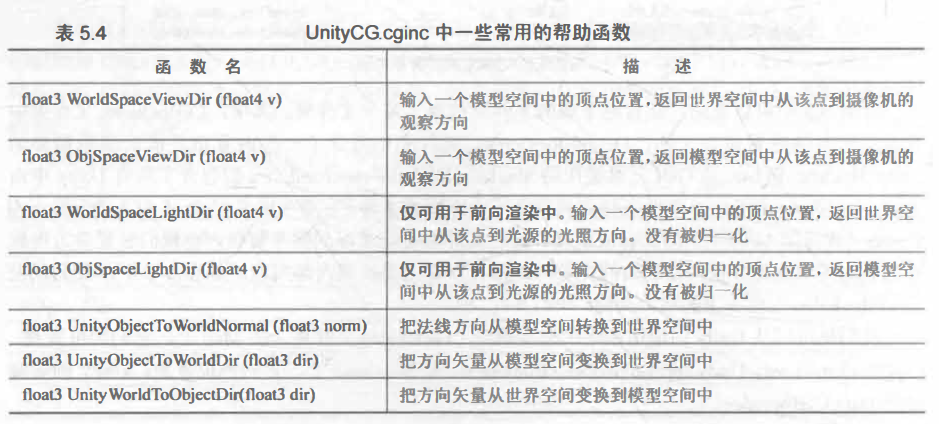
语义
语义的含义
语义就是一个赋给Shader输入和输出的字符串,这个字符串表达了参数的含义。
语义可以让shader知道从哪里读取数据,并把数据输出到哪里。语义描述的变量是不可以随便赋值的,因为流水线需要他们完成特定的任务。
DirectX 10之后出现了以SV(system-value)开头的系统数值语义。
常用的语义


Debug
1.假彩色图像
把需要调试的变量映射到[0, 1]之间, 把它们作为颜色输出到屏幕上,然后通过屏幕上显示的像素颜色来判断这个值是否正确。
struct v2f (
float4 pos : SV POSITION;
fixed4 color : COLORO;
);
v2f vert(appdata_full v) {
v2f o;
o.pos = mul(UNITY MATRIX MVP, v.vertex);
//可视化法线方向
o.color = fixed4(v.normal * 0.5 + fixed3(0.5, 0.5, 0.5), 1.0);
//可视化切线方向
o.color = fixed4 (v.tangent.xyz * 0.5 + fixed3(0.5, 0.5, 0.5),1.0);
//可视化副切线方向
fixed3 binormal = cross(v.normal, v.tangent.xyz) * v.tangent.w;
o.color = fixed4(binormal * 0.5 + fixed3(0.5, 0.5, 0.5), 1.0);
//可视化第一组纹理坐标
o.color = fixed4(v.texcoord.xy, 0.0, 1.0);
//可视化第二组纹理坐标
a.color = fixed4(v.texcoordl.xy, 0.0, 1.0);
//可视化第一组纹理坐标的小数部分
o.color = frac(v.texcoord);
if(any(saturate(v,texcoord)-v.texcoord))
{
	o.color.b=0.5;
}
o.color.a = 1.0;
//可视化第二组纹理坐标的小数部分
o.color = frac(v.texcoordl);
if(any(saturate(v,texcoord1)-v.texcoord1))
{
	o.color.b=0.5;
}
o.color.a = 1.0;
//可视化顶点颜色
//o.color =v.color;
}return o;
fixed4 frag(v2f i) : SV_Target {
return i.color;
}
在这里我们使用的appdata_full几乎包含了所有的模型数据。
2.帧调试器
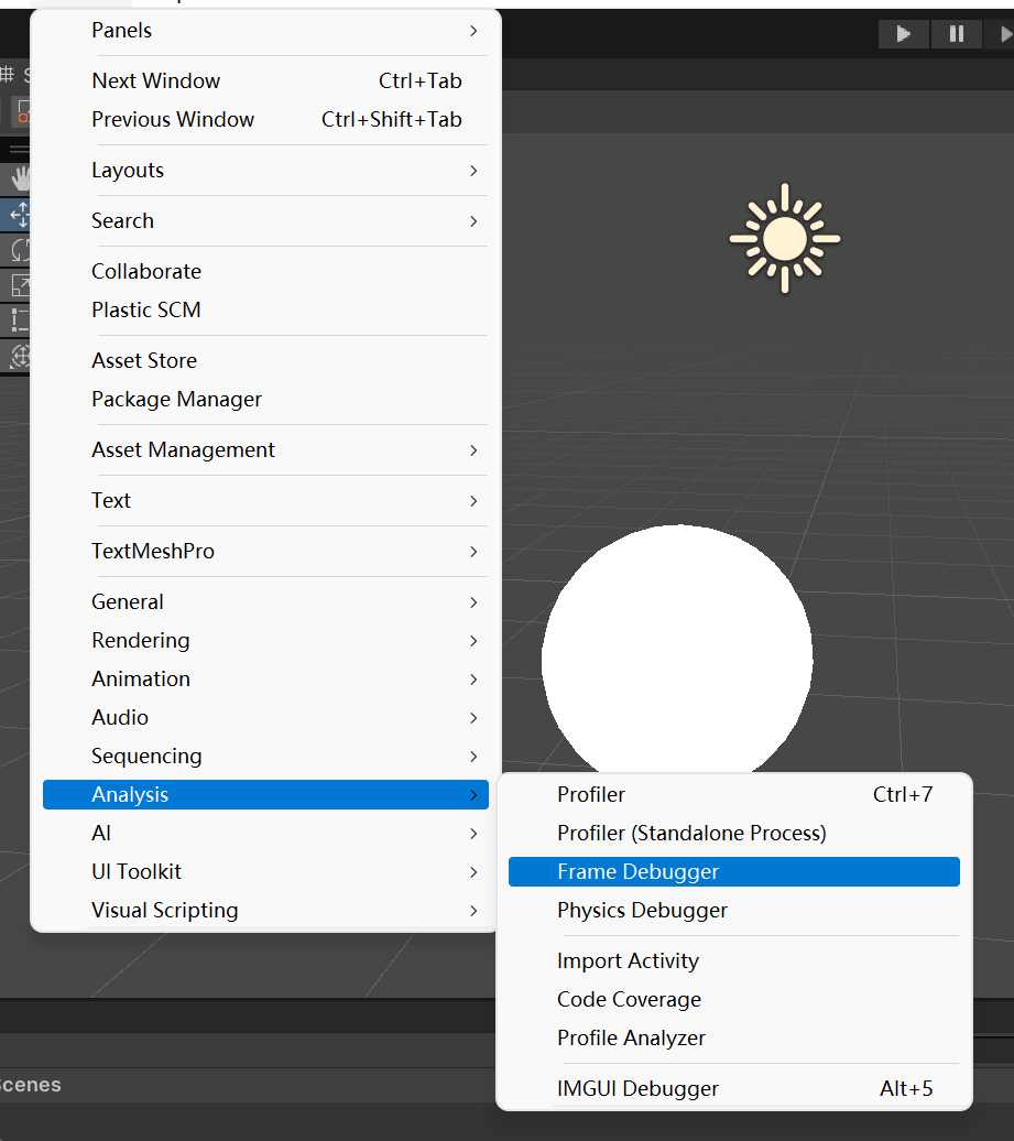
在这里打开
帧调试器可以用于 查看渲染该帧时进行的各种 渲染事件 (event),这些事件包含了 Draw Call序列 ,也包括了类似 清空 帧缓存 等操作。
操作方法
1.最上面的区域可以开启/关闭(单击 Enable 按钮)帧调试功能 ,当开启了帧调试时 ,通过 移动窗口最上方的滑动条(或单击前进和后退按钮) ,我们可以 重放这些渲染事件
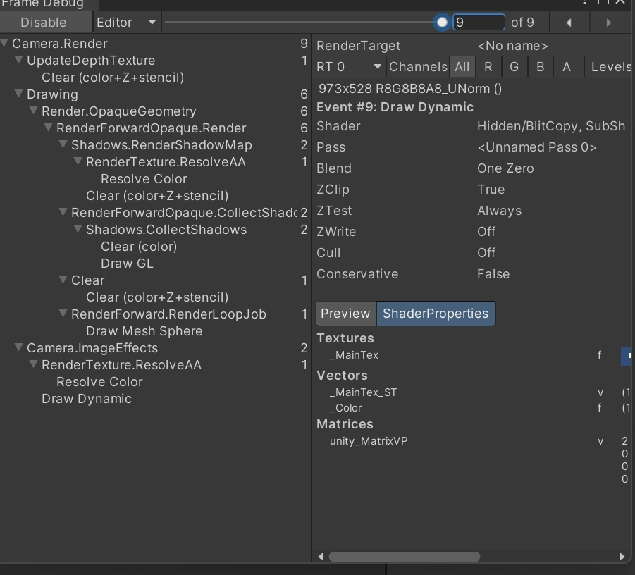
2.左侧的区域显示了所有事件的树状图,在这个树状图中,每个叶子节点就是一个事件 , 而每个父节点的右侧显示了该节点下的事件数目。我们可以从事件的名字了解这个 事件的操作,例如以 Draw 开头的事件通常就是 一 个 Draw Call;
3.当单击了某个事件时 ,在右侧的窗口中 就会显示出该事件的细节 ,例如几何图形的细节以及 使用了哪个 Shader 等。同时在 Game 视图中我们也可以看到它的效果。
渲染平台的差异
我们前面提到了OpenGL 和 DirectX的屏幕空间的差异:
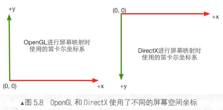
为了应对差异,Unity在很多时候为我们自动翻转,但当我们开启抗锯齿后,Unity便不会为我们自动翻转。
相关文档:https://docs.unity3d.com/Manual/SL-PlatformDifferences.html
规范代码

对于移动平台来说,尽量使用较低的精度
不要使用流程控制语句
基础光照
从宏观的角度来说,渲染包含了两个部分:
- 决定一个像素的可见性
- 决定这个像素上的光照计算
光
光源
在光学里 ,我们一般使用辐照度 (irradiance) 来 量化光。
对于平行光来说 ,它的辐照度可通过计算在垂直于l的单位面积上单位时间内穿过的能量来得到。
如果物体表面与光线不垂直呢?
我们使用光源方向 l 与表面法线 n 之间夹角余弦值来得到(方向矢量模视为1)

可以看出辐照度与cos x 成正比,而cos x 可以通过点积来计算,因此辐照度也通常用点积计算。
吸收和散射
光与物体相交后,会产生两种结果:散射或吸收
散射只改变光线的方向,但不改变光线的密度和颜色。而吸收只改变光线的密度和颜色,但不改变光线的方向。
光线在物体表面经过散射后,有两种方向:一 种将会散射到物体内部,这种现象被称为 折射 (refraction) 或透射 (transmission); 另一种将会散射到外部,这种现象被称为
反射 (reflection)。
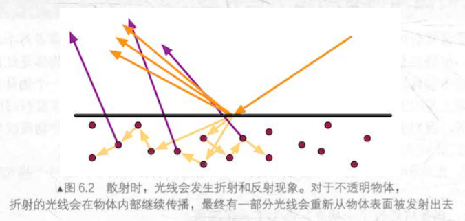
为了区分散射方向,我们用不同的方法来计算他们:高光反射(specular)和漫反射(diffuse)
高光反射:表示物体表面如何反射光线
漫反射:表示有多少光线会被折射,吸收和散射出表面。
根据入射光线的数量和方向,我们可以计算出射光线的数量和方向,我们通常使用 出射度 (exitance) 来描述它。辐照度和出射度之间是满足线性关系的,而它们之间的比值就是材质的漫反射和高光反射属性。
着色
着色(shading)就是根据材质属性(如漫反射属性等)、光源信息(如光源方向、辐照
度等),使用一个等式去计算沿某个观察方向的出射度的过程,这个等式就是光照模型。
BRDF光照模型
BRDF (Bidirectional Reflectance Distribution Function)
在图形学中, BRDF大多使用一 个数学公式来表示, 并且提供了 一 些参数来调整
材质属性。 通俗来讲, 当给定入射光线的方向和辐照度后, BRDF可以给出在某个出 射方向上的光照能量分布。
标准光照模型
标准光照模型值关心直接光照:从光源发射出来照射到物体表面后,只经过一次反射直接进入摄像机的光线。
它把进入摄像机的光线分为四个部分:
- 自发光(emissive)部分,本书使用C emissive来表示。这个部分用于描述当给定一 个方向时,一个表面本身会向该方向发射多少辐射量。需要注意的是,如果没有使用全局光照(global illumination)技术, 这些自发光的表面并不会真的照亮周围的物体, 而是它本身看起来更亮了而已。
- 高光反射(specular)部分, 本书使用 C specular 来表示。 这个部分用于描述当光线从光源照射到模型表面时, 该表面会在完全镜面反射方向散射多少辐射量。
- 漫反射(diffuse)部分, 本书使用 C diffuse 来表示。 这个部分用于描述, 当光线从光源照射到模型表面时, 该表面会向每个方向散射多少辐射量。
- 环境光(ambient)部分, 本书使用 C ambiem 来表示。 它用于描述其他所有的间接光照。
1.环境光
用于描述间接光照
$$
c_a=g_a
$$
a = ambient
2.自发光
光线直接由光源发射进入相机。
$$
c_e=m_e
$$
e = emissive
3.漫反射
对被物体散射的辐射度进行建模,反射方向随机,符合兰伯特定律(Lambert’s law)****:反射光线的强度与表面法线和光源方向之间夹角的余弦值成正比。

n 是表面法线 , I 是指向光源的单位矢量 , m diffese 是材质的漫反射颜色,
C light 是光源颜色。
高光反射
高光反射是一种经验模型,需要知道表面法线、视角方向、光源方向、反射方向等信息。
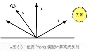
反射方向可以通过其他矢量计算

然后就可以计算高光反射的部分

其中 , m gloss 是材质的光泽度 (gloss), 也被称为反光度 (shininess) 。它用于控制高光区域的“亮点”有多宽 , m gloss 越大,亮点就越小。 m specluar是材质的高光反射颜色, 它用于控制该材质对于高光反射的强度和颜色。 c light 则是光源的颜色和强度。同样, 这里也需要防止点乘的结果为负数。
blinn模型
blinn模型提出了更简单的办法得到类似的效果。
引入了一个新的矢量h,从而避免算反射方向r,
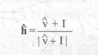
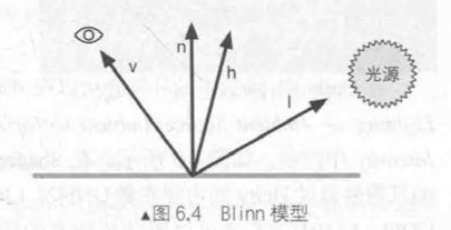
blinn的公式如下:

为了避免点积结果为负,我们进行了max操作。其实还有其他函数可以实现同样的目的,saturate。
函数:saturate(x)
参数:x: 为用于操作的标量或矢量,可以是 float 、 float2 、 float3 等类型。
描述:把 x 截取在 [0, 1]范围内,如果 x 是一个矢量, 那么会对它的每一个分量进行这样的操作。
4.逐像素光照与逐顶点光照
计算光照模型的时候:
1.在片元着色器中计算,也被称为逐像素光照 (per-pixel lighting);
以每个像素为基础,得到法线(对顶点法线插值或者从法线纹理中采样得到),然后进行光照模型的计算。这种在面片之间对顶点法线进行插值的技术被称为 Phong 着色 (Phong shading), 也被称为 Phong 插值或法线插值着色技术。这不同于我们之前讲到的 Phong 光照模型。
2.在顶点着色器中计算 ,也被称为逐顶点光照 (per-vertex lighting) 。
在逐 顶点光照中,我们在每个顶点上计算光照,然后会在渲染图元内部进行线性插值 , 最后输出成像素颜色。由于顶点数小于像素数目,所以逐顶点光照计算量小于逐像素。但逐顶点光照依赖线性插值来得到像素光照,因此光照模型有非线性计算的话(例如高光反射),逐顶点光照就会出问题。
总结
Phong光照模型使用漫反射和高光反射的和 来对反射光照进行建模的基本思想, 并且提出了基于经验的计算高光反射的方法(用于计算漫反射光照的兰伯特模型)。而后, Blinn 的方法简化了计算而且在某些情况下计算更快,这种模型就被称为 Blinn-Phong 光照模型 。
环境光(自发光)
在Shader 中,我们只需要通过 Unity 的内置变量UNITY_LIGHTMODEL_AMBIENT 就可以得到环境光的颜色和强度信息。如果要计算自发光,我们只需要在片元着色器输出最后的颜色之前,把材质的自发光颜色添加到输出颜色上即可。
实现漫反射光照
1.逐顶点
代码如下:
// Upgrade NOTE: replaced 'mul(UNITY_MATRIX_MVP,*)' with 'UnityObjectToClipPos(*)'

Shader "Unity Shader Books/Chapter 6/Diffuse Vertex-Level"
{
    Properties
    {
        _Diffuse("Diffuse",Color)=(1,1,1,1)
        //为了得到并且控制材质的漫反射颜色
    }
    SubShader
    {
        Pass
        {
            Tags{"LightMode"="ForwardBase"}
            //LightMode标签是Pass标签中的一种,它用于定义该Pass在Unity的光照流水线中的角色
            CGPROGRAM
            #pragma vertex vert
            #pragma fragment frag

            #include "Lighting.cginc"
            fixed4 _Diffuse;
            //定义与属性类型相匹配的变量,得到材质的漫反射属性

            struct a2v
            {
                float4 vertex:POSITION;
                float3 normal:NORMAL;
            };

            struct v2f
            {
                float4 pos:SV_POSITION;
                fixed3 color:COLOR;

            };

            v2f vert(a2v v) {
				v2f o;
				// Transform the vertex from object space to projection space
				o.pos = UnityObjectToClipPos(v.vertex);
				//顶点着色器最基本的任务

				//得到环境光
				fixed3 ambient = UNITY_LIGHTMODEL_AMBIENT.xyz;

				// Transform the normal from object space to world space
				fixed3 worldNormal = normalize(mul(v.normal, (float3x3)unity_WorldToObject));


				//得到光源方向(场景光源只有一个且是平行光时,才可以用_WorldSpaceLightPos0得到光源方向)
				fixed3 worldLight = normalize(_WorldSpaceLightPos0.xyz);
				//
				//(法线与光源方向之间的点积)与光源的颜色和强度以及材质的漫反射的颜色相乘即可得到漫反射光照
				fixed3 diffuse = _LightColor0.rgb * _Diffuse.rgb * saturate(dot(worldNormal, worldLight));

				o.color = ambient + diffuse;

				return o;
			}

			fixed4 frag(v2f i) : SV_Target {
				return fixed4(i.color, 1.0);
			}
            //片元着色器输出顶点颜色即可
            ENDCG
        }
    }
	Fallback "Diffuse"
}
效果图:
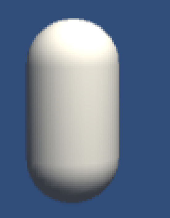
对于细分程度较高的模型 ,逐顶点光照已经可以得到比较好的光照效果了。但对于 一 些细分程度较低的模型,逐顶点光照就会出现一些视觉问题,例如锯齿。
2.逐像素
代码如下:
// Upgrade NOTE: replaced 'mul(UNITY_MATRIX_MVP,*)' with 'UnityObjectToClipPos(*)'

Shader "Unity Shader Books/Chapter 6/Diffuse Pixel-Level"
{
    Properties
    {
        _Diffuse("Diffuse",Color)=(1,1,1,1)
        //为了得到并且控制材质的漫反射颜色
    }
    SubShader
    {
        Pass
        {
            Tags{"LightMode"="ForwardBase"}
            //LightMode标签是Pass标签中的一种,它用于定义该Pass在Unity的光照流水线中的角色
            CGPROGRAM
            #pragma vertex vert
            #pragma fragment frag

            #include "Lighting.cginc"
            fixed4 _Diffuse;
            //定义与属性类型相匹配的变量,得到材质的漫反射属性

            struct a2v
            {
                float4 vertex:POSITION;
                float3 normal:NORMAL;
            };

            struct v2f
            {
                float4 pos:SV_POSITION;
                fixed3 worldNormal:TEXCOORD0;

            };

            v2f vert(a2v v)
            {
				v2f o;
				// Transform the vertex from object space to projection space
                o . pos = UnityObjectToClipPos(v.vertex);
                // Transform the normal from object space to world space
                o . worldNormal = mul(v . normal, (float3x3)unity_WorldToObject);

				return o;
			}

			fixed4 frag(v2f i) : SV_Target {
				fixed3 ambient = UNITY_LIGHTMODEL_AMBIENT.xyz;
			    //得到环境光

				fixed3 worldNormal = normalize(i.worldNormal);
				//把法线归一化

				fixed3 worldLightDir = normalize(_WorldSpaceLightPos0.xyz);
				//得到光线在世界坐标下的方向

				fixed3 diffuse = _LightColor0.rgb * _Diffuse.rgb * saturate(dot(worldNormal,worldLightDir));
				//计算漫反射

				fixed3 color = ambient + diffuse;

				return fixed4(color,1.0);
			}

            ENDCG
        }
    }
	Fallback "Diffuse"
}
逐像素可以得到更平滑的光照效果,但在光线无法到达的区域,模型外观时全黑的,没有明暗变化。
半兰伯特模型
改善了逐像素的缺点

与原兰伯特模型相比,半兰伯特光照模型没有使用 max 操作来防止 n 和 I 的点积
为负值, 而是对其结果进行了一个 a 倍的缩放再加上一个 b 大小的偏移。大多数情况下,a和b的值均为0.5,因此公式为:

通过这样的方式,可以把n.I的结果从[-1,1]映射到[0,1]范围内。半兰伯特模型没有物理依据,只是一个视觉增强技术。
从物体背面看:
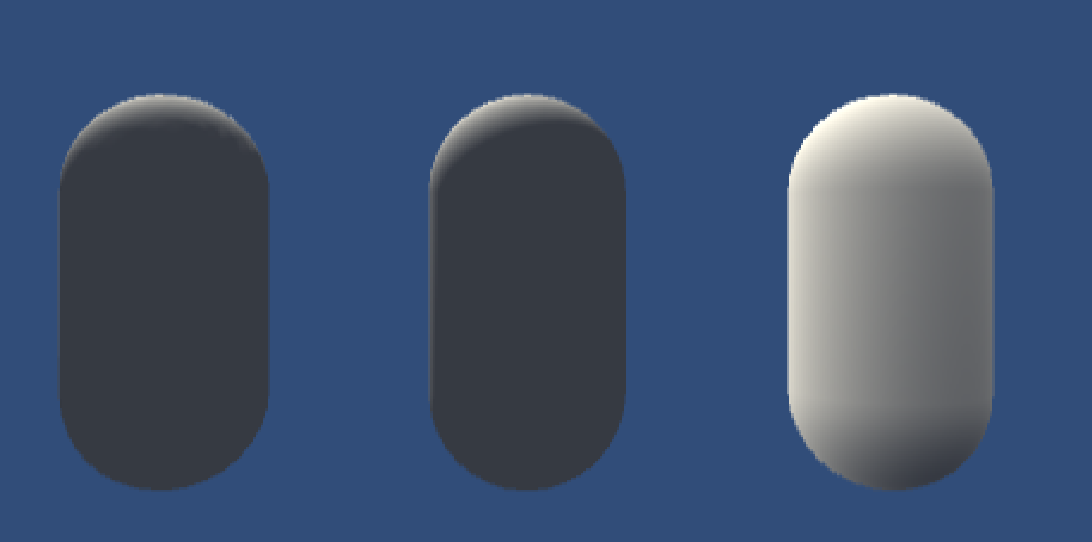
从左到右:逐顶点、逐像素、半兰伯特
高光反射
前面有高光发射的计算公式:
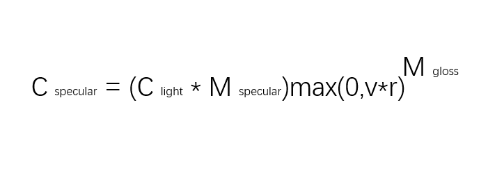
要计算高光反射需要知道 4 个参数 : 入射光线的颜色和强度 C light材质的高光反射系数m specular 视角方向 v 以及反射方向 r 。其中,反射方向 r 可以由表面法线 n 和光源I 计算而得。
$$
r = I - 2(n.I)n
$$
好消息是,除了上式,我们有直接计算反射方向的函数reflect
1.逐顶点
代码如下:
Shader "Unity Shader Books/Chapter 6/SpecularVertexLevel"
{
    Properties
    {
        _Diffuse("Diffuse",Color)=(1,1,1,1)
        _Specular("Specular",Color)=(1,1,1,1)
        _Gloss("Gloss",Range(8.0,256)) = 200
        //声明属性,方便控制参数
    }
    SubShader
    {
        Pass
        {
            Tags{"LightMode" = "ForwardBase"}
            CGPROGRAM
            #pragma vertex vert
            #pragma fragment frag

            #include "Lighting.cginc"
            fixed4 _Diffuse;
            fixed4 _Specular;
            float _Gloss;
            //由于颜色属性的范围在 0 到 1 之间,因此对于_Diffuse和_Specular属性我们可以使用fixed精度的变量来存储
            //而 _Gloss的范围很大,因此我们使用float精度来存储。
            struct a2v
            {
                float4 vertex:POSITION;
                float3 normal:NORMAL;

            };

            struct v2f
            {
                float4 pos:SV_POSITION;
                fixed3 color:COLOR;

            };
            v2f vert(a2v v)
            {
                v2f o;
                o.pos = UnityObjectToClipPos(v.vertex);

                fixed3 ambient = UNITY_LIGHTMODEL_AMBIENT.xyz;

                fixed3 worldNormal = normalize(mul(v.normal,(float3x3)unity_WorldToObject));\


                fixed3 worldLightDir = normalize(_WorldSpaceLightPos0.xyz);
                fixed3 diffuse = _LightColor0.rgb * _Diffuse.rgb * saturate(dot(worldNormal, worldLightDir));


                fixed3 reflectDir = normalize(reflect(-worldLightDir,worldNormal));
                //用reflect函数得到世界空间的反射光线方向

                fixed3 viewDir = normalize(_WorldSpaceCameraPos.xyz-mul(unity_ObjectToWorld,v.vertex));
                //得到世界空间的观察视角方向

                fixed3 specular = _LightColor0.rgb * _Specular.rgb*pow(saturate(dot(reflectDir,viewDir)),_Gloss);
                //计算高光

                o.color = ambient + diffuse +specular;

                return o;

            }
            fixed4 frag(v2f i):SV_Target
            {
                return fixed4(i.color,1.0);

            }
            ENDCG
        }
    }
    FallBack "Specular"
}
效果图:
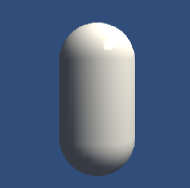
可以看出,高光部分不平滑。这是因为:高光反射部分的计算是非线性的,而在顶点着色器中计算光照再进行插值的过程是线性的,破坏了原计算的非线性关系。
2.逐像素
想得到更平滑的光照,我们需要逐像素。
Shader "Unity Shader Books/Chapter 6/SpecularVertexLevel"
{
    Properties
    {
        _Diffuse("Diffuse",Color)=(1,1,1,1)
        _Specular("Specular",Color)=(1,1,1,1)
        _Gloss("Gloss",Range(8.0,256)) = 200
        //声明属性,方便控制参数
    }
    SubShader
    {
        Pass
        {
            Tags{"LightMode" = "ForwardBase"}
            CGPROGRAM
            #pragma vertex vert
            #pragma fragment frag

            #include "Lighting.cginc"
            fixed4 _Diffuse;
            fixed4 _Specular;
            float _Gloss;
            //由于颜色属性的范围在 0 到 1 之间,因此对于_Diffuse和_Specular属性我们可以使用fixed精度的变量来存储
            //而 _Gloss的范围很大,因此我们使用float精度来存储。
            struct a2v
            {
                float4 vertex:POSITION;
                float3 normal:NORMAL;

            };

            struct v2f
            {
                float4 pos:SV_POSITION;
                fixed3 worldNormal:TEXCOORD0;
                float3 worldPos:TEXCOORD1;

            };
            v2f vert(a2v v)
            {
                v2f o;
                o.pos = UnityObjectToClipPos(v.vertex);

                o.worldPos = mul(unity_ObjectToWorld,v.vertex).xyz;

                o.worldNormal = normalize(mul(v.normal,(float3x3)unity_WorldToObject));\

                return o;

            }
            fixed4 frag(v2f i):SV_Target
            {
                fixed3 ambient = UNITY_LIGHTMODEL_AMBIENT.xyz;

                fixed3 worldNormal = normalize(i.worldNormal);
                fixed3 worldLightDir = normalize(_WorldSpaceLightPos0.xyz);

                fixed3 diffuse = _LightColor0.rgb*_Diffuse.rgb*saturate(dot(worldNormal,worldLightDir));

                fixed3 reflectDir = normalize(reflect(-worldLightDir,worldNormal));

                fixed3 viewDir = normalize(_WorldSpaceCameraPos.xyz-i.worldPos.xyz);
                fixed3 specular = _LightColor0.rgb * _Specular.rgb*pow(saturate(dot(reflectDir,viewDir)),_Gloss);

                return fixed4(ambient+diffuse+specular,1.0);

            }
            ENDCG
        }
    }
    FallBack "Specular"
}
效果图:
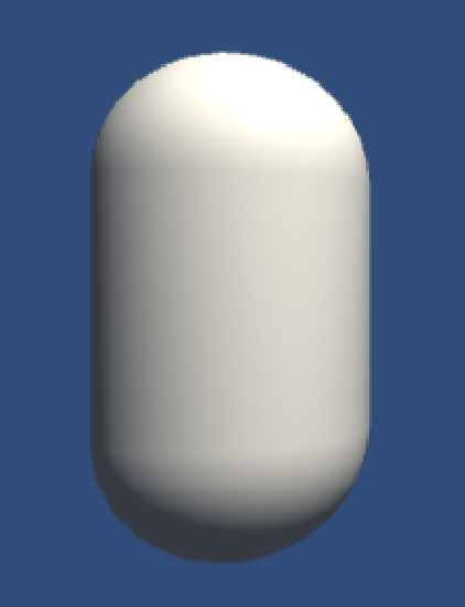
3.Blinn-Phong
代码如下:
Shader "Unity Shader Books/Chapter 6/BlinnPhong"
{
    Properties
    {
        _Diffuse("Diffuse",Color)=(1,1,1,1)
        _Specular("Specular",Color)=(1,1,1,1)
        _Gloss("Gloss",Range(8.0,256)) = 200
        //声明属性,方便控制参数
    }
    SubShader
    {
        Pass
        {
            Tags{"LightMode" = "ForwardBase"}
            CGPROGRAM
            #pragma vertex vert
            #pragma fragment frag

            #include "Lighting.cginc"
            fixed4 _Diffuse;
            fixed4 _Specular;
            float _Gloss;
            //由于颜色属性的范围在 0 到 1 之间,因此对于_Diffuse和_Specular属性我们可以使用fixed精度的变量来存储
            //而 _Gloss的范围很大,因此我们使用float精度来存储。
            struct a2v
            {
                float4 vertex:POSITION;
                float3 normal:NORMAL;

            };

            struct v2f
            {
                float4 pos:SV_POSITION;
                fixed3 worldNormal:TEXCOORD0;
                float3 worldPos:TEXCOORD1;

            };
            v2f vert(a2v v)
            {
                v2f o;
                o.pos = UnityObjectToClipPos(v.vertex);

                o.worldPos = mul(unity_ObjectToWorld,v.vertex).xyz;

                o.worldNormal = normalize(mul(v.normal,(float3x3)unity_WorldToObject));\

                return o;

            }
            fixed4 frag(v2f i):SV_Target
            {
                fixed3 ambient = UNITY_LIGHTMODEL_AMBIENT.xyz;

                fixed3 worldNormal = normalize(i.worldNormal);
                fixed3 worldLightDir = normalize(_WorldSpaceLightPos0.xyz);

                fixed3 diffuse = _LightColor0.rgb*_Diffuse.rgb*saturate(dot(worldNormal,worldLightDir));

                fixed3 reflectDir = normalize(reflect(-worldLightDir,worldNormal));

                fixed3 viewDir = normalize(_WorldSpaceCameraPos.xyz-i.worldPos.xyz);

                fixed3 halfDir = normalize(worldLightDir+viewDir);

                fixed3 specular = _LightColor0.rgb * _Specular.rgb*pow(max(0,dot(worldNormal,halfDir)),_Gloss);

                return fixed4(ambient+diffuse+specular,1.0);

            }
            ENDCG
        }
    }
    FallBack "Specular"
}
效果图:
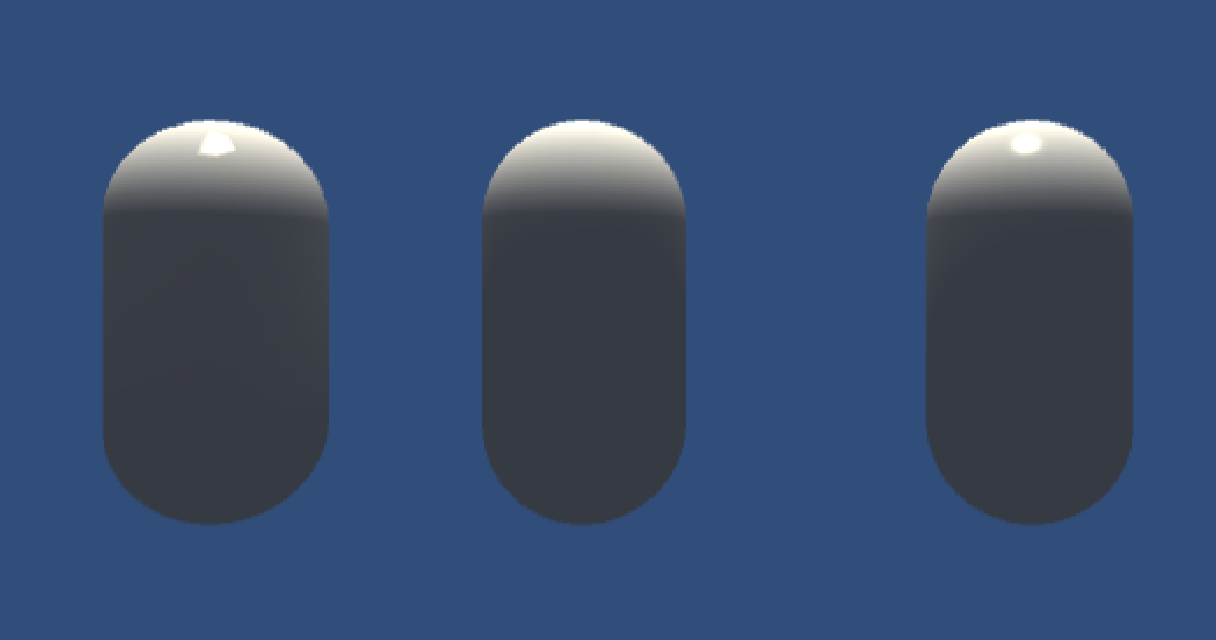
从左到右:逐顶点,逐像素,Blinn-Phong
实际上我们一般使用Blinn-Phong
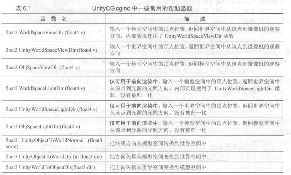
Unity内置函数(表格)
基础纹理
为了控制模型的外观,我们使用纹理映射技术,逐纹素(与像素区分)地控制模型的颜色。纹理映射坐标定义了顶点在纹理中对应的2D坐标,通常用二维变量(u,v)表示,其中u是横向坐标, 而v是纵向坐标。因此, 纹理映射坐标也被称为UV坐标。
在unity中,纹理空间符合OpenGL模式(原点位于左下角)
单张纹理
代码:
Shader "Unity Shader Books/Chapter 7/Single Texture"
{
    Properties
    {
        _Color ("Color Tint", Color) = (1,1,1,1)
        _MainTex ("Main Tex", 2D) = "white" {}
        _Specular("Specular",Color)=(1,1,1,1)
        _Gloss("Gloss",Range(8.0,256))=20
    }
    SubShader
    {
        Pass
        {
            Tags{"LightMode"="ForwardBase"}
            CGPROGRAM

            #pragma vertex vert
            #pragma fragment frag

            #include "Lighting.cginc"

            fixed4 _Color;
            sampler2D _MainTex;
            float4 _MainTex_ST;
            //使用纹理名_ST的方式来声明某个纹理的属性。其中,ST是缩放(scale)和平移(translation)的缩写。
            //_MainTex_ST可以让我们得到该纹理的缩放和平移 偏移)值,_MainTex_ST.xy 存储的是缩放值,
            //而_MainTex_ST.zw 存储的是偏移值 。这些值可以在材质面板的纹理属性中调节
            fixed4 _Specular;
            float _Gloss;

            struct a2v
            {
                float4 vertex:POSITION;
                float3 normal:NORMAL;
                float4 texcoord:TEXCOORD0;

            };

            struct v2f
            {
                float4 pos:SV_POSITION;
                float3 worldNormal:TEXCOORD0;
                float3 worldPos:TEXCOORD1;
                float2 uv:TEXCOORD2;

            };

            v2f vert(a2v v)
            {
                v2f o;
                o.pos = UnityObjectToClipPos(v.vertex);
                o.worldNormal=UnityObjectToWorldNormal(o.worldNormal);
                o.worldPos=mul(unity_ObjectToWorld,v.vertex).xyz;
                o.uv = v.texcoord.xy*_MainTex_ST.xy+_MainTex_ST.zw;
                //先缩放,再偏移
                return o;
            }
            fixed4 frag(v2f i):SV_Target
            {
                fixed3 worldNormal=normalize(i.worldNormal);
                fixed3 worldLightDir = normalize(UnityWorldSpaceLightDir(i.worldPos));
                fixed3 albedo = tex2D(_MainTex,i.uv).rgb*_Color.rgb;
                //使用纹理对漫反射采样
                fixed3 ambient = UNITY_LIGHTMODEL_AMBIENT.xyz*albedo;
                fixed3 diffuse = _LightColor0.rgb*albedo*max(0,dot(worldNormal,worldLightDir));

                fixed3 viewDir = normalize(UnityWorldSpaceViewDir(i.worldPos));
                fixed3 halfDir = normalize(worldLightDir+viewDir);
                fixed3 specular = _LightColor0.rgb*_Specular.rgb*pow(max(0,dot(worldNormal,halfDir)),_Gloss);
                return fixed4(ambient+diffuse+specular,1.0);
            }


            ENDCG
        }
    }
    FallBack "Specular"
}
效果图:
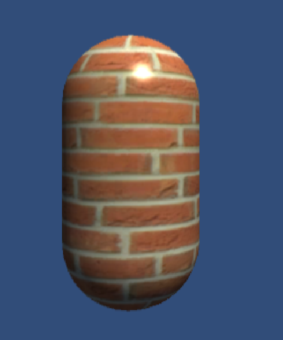
纹理属性
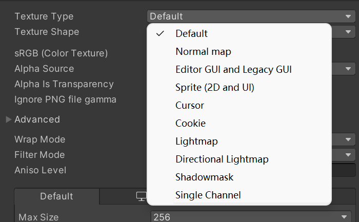
为导入的纹理选择合适的类型,从而得到更好的优化。
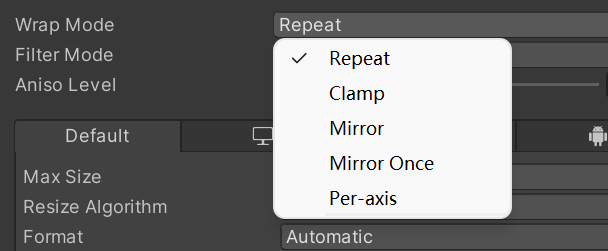
wrap mode
决定了纹理坐标超过[0,1]范围之后如何被平铺。
如果是repeat,则纹理不断重复。
如果是clamp,则是截取:大于1的数截取到1,小于0的数字截取到0

Filter Mode
决定了纹理由于变换产生的拉伸用哪种滤波形式:Point, Bilinear以及Trilinear
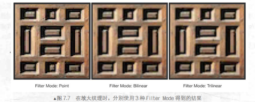
它们得到的图片滤波效果依次提升,但需要耗费的性能也依次增大。纹理滤波也会影响放大或缩小纹理时得到的图片质量。
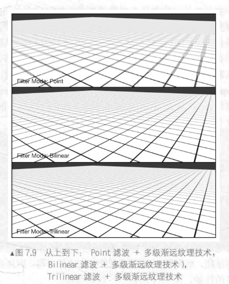
纹理缩小的过程比放大更加复杂一些,此时原纹理中的多个像素将会对应一个目标像素。纹理缩小更加复杂的原因就是:需要处理抗锯齿问题,一个最常使用的方法就是使用多级渐远纹理(mip mapping)技术。
多级渐远纹理技术,将原纹理提前用滤波处理来得到很多更小的图像, 形成了一个图像金字塔, 每一层都是对上一层图像降采样的结果。这样在实时运行时,就可以快速得到结果像素,例如当物体远离摄像机时,可以直接使用较小的纹理。 但缺点是需要使用一定的空间用于存储这些多级渐远纹理, 通常会多占用33%的内存空间。
在内部实现上, Point模式使用了最近邻(nearest neighbor)滤波, 在放大或缩小时, 它的采样像素数目通常只有 一 个, 因此图像会看起来有种像素风格的效果。
而Bilinear滤波则使用了线性滤波, 对于每个目标像素, 它会找到4个邻近像素, 然后对它们进行线性插值混合后得到最终像素, 因此图像看起来像被模糊了。
而Trilinear滤波几乎是和Bilinear 一样的, 只是Trilinear还会在多级渐远纹理之间进行混合。 如果一张纹理没有用mip mapping,那么trilinear和bilinear效果相同
凹凸映射
凹凸映射的目的是使用一张纹理来修改模型表面的法线,以便为模型提供更多的细节。这种方法不会真的改变模型的顶点位置,只是让模型看起来好像是“凹凸不平”的,但可以从模型的轮廓处看出“破绽”。
1.高度纹理
用一张高度图来实现凹凸映射。存储的是强度值(intensity),颜色越浅表示越往外凸起,越深表示越往里凹。
优点:直观
缺点:计算量大,复杂
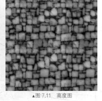
2.法线纹理
法线纹理就是存储表面的法线方向,由于法线方向 的分量范围在 [-1, l] , 而像素的分
量范围为 [0, 1], 因此我们需要做一个映射:
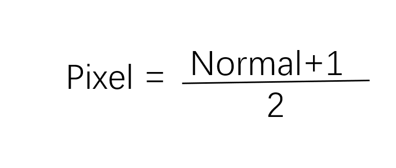
这就要求,我们在 Shader中对法线纹理进行纹理采样后,还需要对结果进行一次反映射的过程,以得到原先的法线方向。反映射就是使用上面映射函数的逆函数 :
$$
normal = pixel*2-1
$$
对于模型顶点自带的法线,它们是定义在模型空间中的,因此一种直接的想法就是将修改后的模型空间中的表面法线存储在一张纹理中,这种纹理被称为是模型空间的法线纹理 (object-space normal map) 。然而,在实际制作中,我们往往会采用另一种坐标空间,即模型顶点的切线空间(tangent space) 来存储法线。
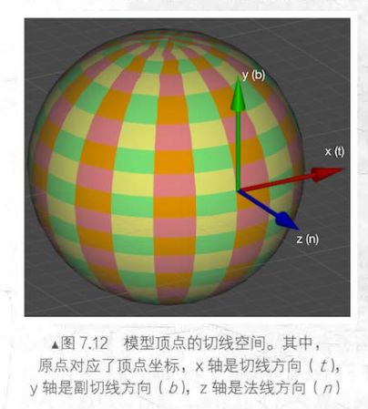
对于模型的每个顶点,它都有一个属千自己的切线空间,这个切线空间的原点就是该顶点本身,而 z 轴是顶点的法线方向 (n) , X 轴是顶点的切线方向 (t), 而 y 轴可由法线和切线叉积而得,也被称为是副切线 C(bitangent, b) 或副法线。这种纹理就被称为切线空间的法线纹理。
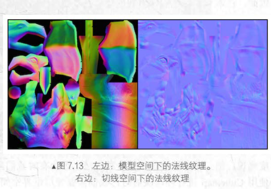
模型空间下的法线纹理看起来是“五颜六色”的。这是因为所有法线所在的坐标空间是同一个坐标空间,即模型空间,而每个点存储的法线方向是各异的,例如有的是 (0,1, 0), 经过映射后存储到纹理中就对应了 RGB(0.5, 1, 0.5) 浅绿色。
而切线空间下的法线纹理看起来几乎全部是浅蓝色的 。这是因为,每个法线方向所在的坐标空间是不一样的,即是表面每点各自的切线空间。这种法线纹理其实就是存储了每个点在各自的切线空间中的法线扰动方向。也就是说,如果一个点的法线方向不变,那么在它的切线空间中,新的法线方向就是 z 轴方向,即值为 (0,0, 1), 经过映射后存储在纹理中就对应了 RGB(0.5, 0.5, 1) 浅蓝色 。而这个颜色就是法线纹理中大片的蓝色。这些蓝色实际上说明顶点的大部分法线是和模型本身法线一样的,不需要改变
模型空间存储法线的优点:
- 实现简单 ,更加 直观。我们甚至都不需要模型原始的法线和切线等信息 ,也就是说,计算更少。生成它也非常简单 ,而如果要 生成切线空间下的法线纹理,由千模型的切线一般是和 UV 方向相同,因此想要得到效果比较好的法线映射就要求纹理映射也是连续的。
- 在纹理坐标的缝合处和尖锐的边角部分,可见的突变(缝隙)较少,即可以提供平滑的边界。这是因为模型空间下的法线纹理存储的是同一坐标系下的法线信息,因此在边界处通过插值得到的法线可以平滑变换。而切线空间下的法线纹理中的法线信息是依靠纹理坐标的方向得到的结果,可能会在边缘处或尖锐的部分造成更多可见的缝合迹象
切线空间存储法线的优点:
- 自由度很高。模型空间下的法线纹理记录的是绝对法线信息,仅可用千创建它时的那个模型,而应用到其他模型上效果就完全错误了。而切线空间下的法线纹理记录的是相对法线信息,这意味着,即便把该纹理应用到一个完全不同的网格上,也可以得到一个合理的结果。
- 可进行 UV 动画。比如,我们可以移动 一 个纹理的 UV 坐标来实现一个凹凸移动的效果,
- 但使用模型空间下的法线纹理会得到完全错误的结果。原因同上。这种 UV 动画在水或火山熔岩这种类型的物体上会经常用到 。
- 可以重用法线纹理。比如,一个砖块,我们仅使用一张法线纹理就可以用到所有的 6 个面上。原因同上。
- 可压缩。由于切线空间下的法线纹理中法线的 Z 方向总是正方向,因此我们可以仅存储XY 方向,而推导 得到 Z 方向。而模型空间下的法线纹理由于每个方向都是可能的,因此必须存储 3 个方向的值,不可压缩。
综上,我们更喜欢切线空间。
3.实践凹凸映射
1.在切线空间下计算
在片元着色器中通过纹理采样得到切线空间下的法线,然后再与切线空间下的视角方向、光照方向等进行计算,得到最终的光照结果 。因此,需要在顶点着色器中把视角方向和光照方向从模型空间变换到切线空间中。
代码:
// Upgrade NOTE: replaced 'mul(UNITY_MATRIX_MVP,*)' with 'UnityObjectToClipPos(*)'

Shader "Unity Shader Books/Chapter 7/Normal Map In Tangent Space" {
	Properties {
		_Color ("Color Tint", Color) = (1, 1, 1, 1)
		_MainTex ("Main Tex", 2D) = "white" {}
		_BumpMap ("Normal Map", 2D) = "bump" {}
		_BumpScale ("Bump Scale", Float) = 1.0
		_Specular ("Specular", Color) = (1, 1, 1, 1)
		_Gloss ("Gloss", Range(8.0, 256)) = 20
	}
	SubShader {
		Pass {
			Tags { "LightMode"="ForwardBase" }

			CGPROGRAM

			#pragma vertex vert
			#pragma fragment frag

			#include "Lighting.cginc"

			fixed4 _Color;
			sampler2D _MainTex;
			float4 _MainTex_ST;
			//使用纹理名_ST的方式来声明某个纹理的属性。其中,ST是缩放(scale)和平移(translation)的缩写。
            //_MainTex_ST可以让我们得到该纹理的缩放和平移 偏移)值,_MainTex_ST.xy 存储的是缩放值,
			sampler2D _BumpMap;
			float4 _BumpMap_ST;
			float _BumpScale;
			fixed4 _Specular;
			float _Gloss;

			struct a2v {
				float4 vertex : POSITION;
				float3 normal : NORMAL;
				float4 tangent : TANGENT;
				float4 texcoord : TEXCOORD0;
			};

			struct v2f {
				float4 pos : SV_POSITION;
				float4 uv : TEXCOORD0;
				float3 lightDir: TEXCOORD1;
				float3 viewDir : TEXCOORD2;
			};

			v2f vert(a2v v) {
				v2f o;
				o.pos = UnityObjectToClipPos(v.vertex);

				o.uv.xy = v.texcoord.xy * _MainTex_ST.xy + _MainTex_ST.zw;
				o.uv.zw = v.texcoord.xy * _BumpMap_ST.xy + _BumpMap_ST.zw;

				// Construct a matrix that transforms a point/vector from tangent space to world space
				fixed3 worldNormal = UnityObjectToWorldNormal(v.normal);
				fixed3 worldTangent = UnityObjectToWorldDir(v.tangent.xyz);
				fixed3 worldBinormal = cross(worldNormal, worldTangent) * v.tangent.w;


				//wToT = the inverse of tToW = the transpose of tToW as long as tToW is an orthogonal matrix.
				float3x3 worldToTangent = float3x3(worldTangent, worldBinormal, worldNormal);

				// Transform the light and view dir from world space to tangent space
				o.lightDir = mul(worldToTangent, WorldSpaceLightDir(v.vertex));
				o.viewDir = mul(worldToTangent, WorldSpaceViewDir(v.vertex));

				return o;
			}

			fixed4 frag(v2f i) : SV_Target {
				fixed3 tangentLightDir = normalize(i.lightDir);
				fixed3 tangentViewDir = normalize(i.viewDir);

				// Get the texel in the normal map
				fixed4 packedNormal = tex2D(_BumpMap, i.uv.zw);
				//使用tex2D对法线纹理采样
				fixed3 tangentNormal;

				tangentNormal = UnpackNormal(packedNormal);
				tangentNormal.xy *= _BumpScale;
				tangentNormal.z = sqrt(1.0 - saturate(dot(tangentNormal.xy, tangentNormal.xy)));

				fixed3 albedo = tex2D(_MainTex, i.uv).rgb * _Color.rgb;


				fixed3 ambient = UNITY_LIGHTMODEL_AMBIENT.xyz * albedo;

				fixed3 diffuse = _LightColor0.rgb * albedo * max(0, dot(tangentNormal, tangentLightDir));

				fixed3 halfDir = normalize(tangentLightDir + tangentViewDir);
				fixed3 specular = _LightColor0.rgb * _Specular.rgb * pow(max(0, dot(tangentNormal, halfDir)), _Gloss);

				return fixed4(ambient + diffuse + specular, 1.0);
			}

			ENDCG
		}
	}
	FallBack "Specular"
}
效果图:
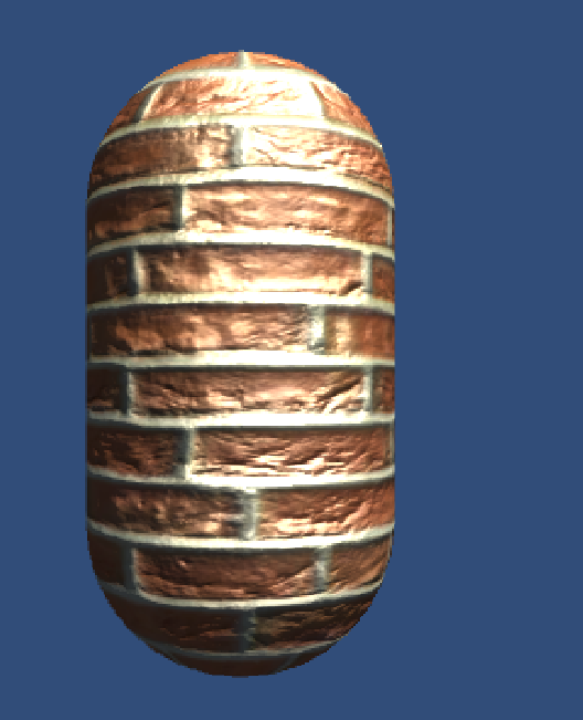
2.在世界空间下计算
在顶点着色器中计算从切线空间到世界空间的变换矩阵,并把它传递给片元着色器。
变换矩阵的计算可以由顶点的切线、副切线和法线在世界空间下的表示来得到。
最 后,我们只需要在片元着色器中把法线纹理中的法线方向从切线空间变换到世界空间下即可。尽管这种方法需要更多的计算,但在需要使用 Cubemap进行环境映射等情况下,我们就需要使用这种方法。
代码如下:
// Upgrade NOTE: replaced 'mul(UNITY_MATRIX_MVP,*)' with 'UnityObjectToClipPos(*)'

Shader "Unity Shader Books/Chapter 7/Normal Map In World Space" {
	Properties {
		_Color ("Color Tint", Color) = (1, 1, 1, 1)
		_MainTex ("Main Tex", 2D) = "white" {}
		_BumpMap ("Normal Map", 2D) = "bump" {}
		_BumpScale ("Bump Scale", Float) = 1.0
		_Specular ("Specular", Color) = (1, 1, 1, 1)
		_Gloss ("Gloss", Range(8.0, 256)) = 20
	}
	SubShader {
		Pass {
			Tags { "LightMode"="ForwardBase" }

			CGPROGRAM

			#pragma vertex vert
			#pragma fragment frag

			#include "Lighting.cginc"

			fixed4 _Color;
			sampler2D _MainTex;
			float4 _MainTex_ST;
			//使用纹理名_ST的方式来声明某个纹理的属性。其中,ST是缩放(scale)和平移(translation)的缩写。
            //_MainTex_ST可以让我们得到该纹理的缩放和平移 偏移)值,_MainTex_ST.xy 存储的是缩放值,
			sampler2D _BumpMap;
			float4 _BumpMap_ST;
			float _BumpScale;
			fixed4 _Specular;
			float _Gloss;

			struct a2v {
				float4 vertex : POSITION;
				float3 normal : NORMAL;
				float4 tangent : TANGENT;
				float4 texcoord : TEXCOORD0;
			};

			struct v2f {
				float4 pos : SV_POSITION;
				float4 uv : TEXCOORD0;
				float4 TtoW0:TEXCOORD1;
				float4 TtoW1:TEXCOORD2;
				float4 TtoW2:TEXCOORD3;
				//把矩阵拆分成多个变量存储
			};

			v2f vert(a2v v) {
				v2f o;
				o.pos = UnityObjectToClipPos(v.vertex);

				o.uv.xy = v.texcoord.xy * _MainTex_ST.xy + _MainTex_ST.zw;
				o.uv.zw = v.texcoord.xy * _BumpMap_ST.xy + _BumpMap_ST.zw;

				float3 worldPos=mul(unity_ObjectToWorld,v.vertex).xyz;
				fixed3 worldNormal=UnityObjectToWorldNormal(v.normal);
				fixed3 worldTangent=UnityObjectToWorldDir(v.tangent.xyz);
				fixed3 worldBinormal=cross(worldNormal,worldTangent)*v.tangent.w;

				o.TtoW0 = float4(worldTangent.x, worldBinormal.x,worldNormal.x,worldPos.x);
				o.TtoW1 = float4(worldTangent.y, worldBinormal.y,worldNormal.y,worldPos.y);
				o.TtoW2 = float4(worldTangent.z, worldBinormal.z,worldNormal.z,worldPos.z);
				return o;
			}

			fixed4 frag(v2f i) : SV_Target {
				float3 worldPos = float3(i.TtoW0.w,i.TtoW1.w,i.TtoW2.w);
				fixed3 lightDir=normalize(UnityWorldSpaceLightDir(worldPos));
				fixed3 viewDir = normalize(UnityWorldSpaceViewDir(worldPos));

				fixed3 bump=UnpackNormal(tex2D(_BumpMap,i.uv.zw));
				bump.xy*=_BumpScale;
				bump.z=sqrt(1.0-saturate(dot(bump.xy,bump.xy)));
				bump=normalize(half3(dot(i.TtoW0.xyz,bump),dot(i.TtoW1.xyz,bump),dot(i.TtoW2.xyz,bump)));


				fixed3 albedo = tex2D(_MainTex, i.uv).rgb * _Color.rgb;


				fixed3 ambient = UNITY_LIGHTMODEL_AMBIENT.xyz * albedo;

				fixed3 diffuse = _LightColor0.rgb * albedo * max(0, dot(bump,lightDir));

				fixed3 halfDir = normalize(lightDir + viewDir);
				fixed3 specular = _LightColor0.rgb * _Specular.rgb * pow(max(0, dot(bump, halfDir)), _Gloss);

				return fixed4(ambient + diffuse + specular, 1.0);
			}

			ENDCG
		}
	}
	FallBack "Specular"
}
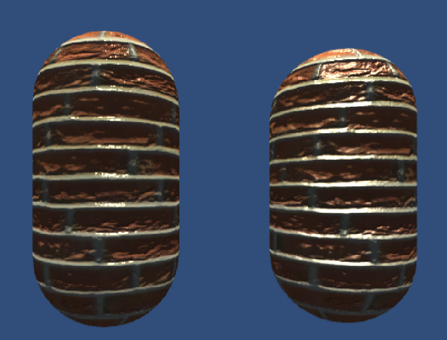
左:切线空间 右:世界空间
4.为什么法线纹理类型用Normal Map
这么做可以让 Unity 根据不同平台对纹理进行压缩。再通过 UnpackNormal 函数来针对不同的压缩格式对法线纹理进行正确的采样。

Create from Grayscale是从高度图中生成法线纹理的。
当勾选了 Create from Grayscale 后,还多出了两个选项-—-Bumpiness 和Filtering 。其中Bumpiness 用于控制凹凸程度,而 Filtering 决定我们使用哪种方式来计算凹凸程度 , 它有两种选项:一种是 Smooth , 这使得生成后的法线纹理会比较平滑;另一种是 Sharp , 它会使用 Sobel 滤波(一种边缘检测时使用的滤波器)来生成法线。
渐变纹理
渐变纹理可以用来控制漫反射光照效果。
Shader "Unity Shader Books/Chapter 7/RampTexture"
{
    Properties
    {
        _Color ("Color Tint", Color) = (1, 1, 1, 1)
		_RampTex("Ramp Tex",2D)="white"{}
		_Specular ("Specular", Color) = (1, 1, 1, 1)
		_Gloss ("Gloss", Range(8.0, 256)) = 20
    }
    SubShader
    {
        Pass
        {
            Tags{"LightMode"="ForwardBase"}
            CGPROGRAM
            #pragma vertex vert
            #pragma fragmemt frag
            #include "Lighting.cginc"

            fixed4 _Color;
            sampler2D _RampTex;
            float4 _RampTex_ST;
            fixed4 _Specular;
            float _Gloss;

            struct a2v
            {
                float4 vertex:POSITION;
                float3 normal:NORMAL;
                float4 texcoord:TEXCOORD0;
            };

            struct v2f
            {
                float4 pos:SV_POSITION;
                float3 worldNormal:TEXCOORD0;
                float3 worldPos:TEXCOORD1;
                float2 uv:TEXCOORD2;

            };
            v2f vert(a2v v)
            {
                v2f o;
                o.pos = UnityObjectToClipPos(v.vertex);
                o.worldNormal=UnityObjectToWorldNormal(v.normal);
                o.worldPos = mul(unity_ObjectToWorld,v.vertex).xyz;
                o.uv = TRANSFORM_TEX(v.texcoord,_RampTex);
                return o;

            }
            fixed4 frag(v2f i):SV_Target
            {
                fixed3 worldNormal=normalize(i.worldNormal);
                fixed3 worldLightDir = normalize(i.worldPos);
                fixed3 ambient=UNITY_LIGHTMODEL_AMBIENT.xyz;
                fixed halfLambert=0.5*dot(worldNormal,worldLightDir)+0.5;
                //半兰伯特模型,对法线方向和光照方向的点做一次0.5倍缩放和0.5大小的偏移
                fixed3 diffuseColor=tex2D(_RampTex,fixed2(halfLambert,halfLambert)).rgb*_Color.rgb;

                fixed3 diffuse=_LightColor0.rgb*diffuseColor;
                fixed3 viewDir=normalize(UnityWorldSpaceViewDir(i.worldPos));
                fixed3 halfDir=normalize(worldLightDir+viewDir);

                fixed3 specular=_LightColor0.rgb*_Specular.rgb*pow(max(0,dot(worldNormal,halfDir)),_Gloss);
                return fixed4(ambient+diffuse+specular,1.0);
            }
            ENDCG
        }
    }
    FallBack "Specular"
}
遮罩纹理
使用遮罩纹理的流程一般是:通过采样得到遮罩纹理的纹素值,然后使用其中某个(或某几个)通道的值(例如 texel.r) 来与某种表面属性进行相乘,这样,当该通道的值为 0 时,可以保护表面不受该屈性的影响。总而言之, 使用遮罩纹理我们更加精准(像素级别)地控制模型表面的各种性质。
实践遮罩纹理
代码如下:
// Upgrade NOTE: replaced 'mul(UNITY_MATRIX_MVP,*)' with 'UnityObjectToClipPos(*)'

Shader "Unity Shader Books/Chapter 7/Mask Texture"
{
    Properties
    {
        _Color ("Color Tint", Color) = (1, 1, 1, 1)
		_MainTex ("Main Tex", 2D) = "white" {}
		_BumpMap ("Normal Map", 2D) = "bump" {}
		_BumpScale ("Bump Scale", Float) = 1.0
        _SpecularMask("Specular Mask",2D)="white"{}
        _SpecularScale("Specular Scale",Float)=1.0
        //_SpecularMask是高光反射遮罩纹理,_SpecularScaJe则是用于控制遮罩影响度的系数
		_Specular ("Specular", Color) = (1, 1, 1, 1)
		_Gloss ("Gloss", Range(8.0, 256)) = 20
    }
    SubShader
    {
        Pass
    	{
    		Tags{"LightMode"="ForwardBase"}
    		CGPROGRAM
    		#pragma vertex vert
    		#pragma fragment frag
    		#include "Lighting.cginc"

    		fixed4 _Color ;
			sampler2D _MainTex ;
			float4 _MainTex_ST;
			sampler2D _BumpMap;
			float _BumpScale;
			sampler2D _SpecularMask ;
			float _SpecularScale;
			fixed4 _Specular;
			float _Gloss;

		    struct a2v
		    {
			    float4 vertex:POSITION;
		    	float3 normal:NORMAL;
		    	float4 tangent:TANGENT;
		    	float4 texcoord:TEXCOORD0;

		    };

		    struct v2f
		    {
			    float4 pos:SV_POSITION;
		    	float2 uv:TEXCOORD0;
		    	float3 lightDir:TEXCOORD1;
		    	float3 viewDir:TEXCOORD2;

		    };
    		v2f vert(a2v v)
    		{
    			v2f o;
    			o.pos = UnityObjectToClipPos(v.vertex);
    			o.uv.xy=v.texcoord.xy*_MainTex_ST.xy+_MainTex_ST.zw;
    			TANGENT_SPACE_ROTATION;
    			o.lightDir=mul(rotation,ObjSpaceLightDir(v.vertex)).xyz;
    			o.viewDir=mul(rotation,ObjSpaceViewDir(v.vertex)).xyz;
    			return o;
    		}
    		fixed4 frag(v2f i):SV_Target
    		{
    			fixed3 tangentLightDir = normalize(i.lightDir);
    			fixed3 tangentViewDir = normalize(i.viewDir);

    			fixed3 tangentNormal=UnpackNormal(tex2D(_BumpMap,i.uv));
    			tangentNormal.xy*=_BumpScale;
    			tangentNormal.z=sqrt(1.0-saturate(dot(tangentNormal.xy,tangentNormal.xy)));
				fixed3 albedo=tex2D(_MainTex,i.uv).rgb*_Color.rgb;

    			fixed3 ambient=UNITY_LIGHTMODEL_AMBIENT.xyz*albedo;
    			fixed3 diffuse = _LightColor0.rgb*albedo*max(0,dot(tangentNormal,tangentLightDir));

    			fixed3 halfDir=normalize(tangentLightDir+tangentViewDir);
    			fixed specularMask=tex2D(_SpecularMask,i.uv).r*_SpecularScale;
    			//首先对遮罩纹理_SpecularMask采样,随后使用r分量计算掩码值,然后与_SpecularScale相乘,控制高光反射强度
    			fixed3 specular=
    				_LightColor0.rgb*_Specular.rgb*pow(max(0,dot(tangentNormal,halfDir)),_Gloss)*specularMask;
    			return fixed4(ambient+diffuse+specular,1.0);
    		}
    		ENDCG
        }
    }
    FallBack "Specular"
}
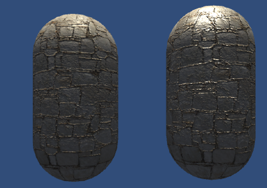
左:使用遮罩纹理。右:不使用遮罩纹理。
其他用途
在实践中,遮罩纹理已经不仅保护某些区域使它们免于某些修改,而是可以存储任何我们希望逐像素控制的表面属性。
通常,我们会充分利用一张纹理的 RGBA 四个通道 ,用于存储不同的属性 。例如,我们可以把高光反射的强度存储在 R 通道,把边缘光照的强度存储在G通道,把高光反射的指数部分存储在B通道,最后把自发光强度存储在A通道。
透明效果
在 Unity 中,我们通常使用两种方法来实现透明效果:第一种是使用透明度测(Alpha Test),这种方法其实无法得到真正的半透明效果;另一种是 透明度混合 (Alpha Blending)。
由于强大的深度缓冲,对于不透明物体,渲染顺序如何对于场景无影响。
深度缓冲可以决定哪个物体在前面,哪些物体会被遮挡,从而可以在实时渲染中解决可见性。
它的原理是:根据深度缓存中的值来判断该片元距离摄像机的距离,当渲染一个片元时,需要把它的深度值和已经存在于深度缓冲中的值进行比较(如果开启了深度测试,如果它的值距离摄像机更远,那么说明这个片元不应该被渲染到屏幕上(有物体挡住了它);否则,这个片元应该覆盖掉此时颜色缓冲中的像素值,并把它的深度值更新到深度缓冲中(如果开启了深度写入)。
但使用透明度混合时,我们会关闭深度写入。
为什么关闭深度写入呢?
主要还是半透明的处理。
如果不关闭深度写入,一个半透明表面背后的表面本来是可以透过它被我们看到的, 但由于深度测试时判断结果是该半透明表面距离摄像机更近, 导致后面的表面将会被剔除, 我们也就无法透过半透明表面看到后面的物体了。
注意半透明物体的渲染顺序:
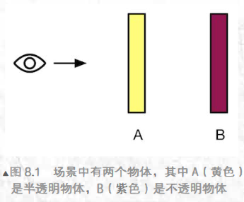
- 我们先渲染B, 再渲染A。那么由于不透明物体开启了深度测试和深度写入,而此时深度缓冲中没有任何有效数据, 因此B首先会写入颜色缓冲和深度缓冲。 随后我
们渲染A, 透明物体仍然会进行深度测试, 因此我们A距离摄像机更近,因此, 我们会使用A的透明度来和颜色缓冲中的B的颜色进行混合, 得到正确的半透明效果 - 我们先渲染A,再渲染B。渲染A时,深度缓冲区中没有任何有效数据,因此A直接写入颜色缓冲, 但由于对半透明物体关闭了深度写入, 因此A不会修改深度缓冲。等到渲染B时, B会进行深度测试, 它发现,“咦, 深度缓存中还没有人来过, 那我就放心地写入颜色缓冲了! “‘ 结果就是B会直接覆盖A的颜色。 从视觉上来看, B就出现在了A的前面, 而这是错误的。
所以渲染引擎会对物体先排序,再渲染:
先渲染所有不透明物体,并开启它们的深度测试和深度写入。
把半透明物体按它们距离摄像机的远近进行排序,然后按照从后往前的顺序渲染这些半透明物体,并开启它们的深度测试,但关闭深度写入。
Unity的渲染队列
可以使用SubShader的Queue标签决定模型归于哪个队列。
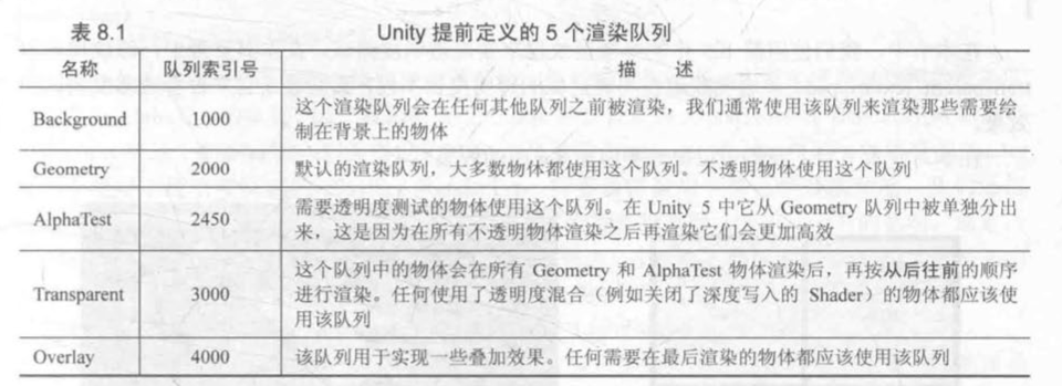
透明度测试
原理:
它采用一种“霸道极端”的机制,只要一个片元的透明度不满足条件(通常是小于某个阙值),那么它对应的片元就会被舍弃。被舍弃的片元将不会再进行任何处理,也不会对颜色缓冲产生任何影响;否则,就会按照普通的不透明物体的处理方式来处理它,
即进行深度测试、深度写入等。也就是说,透明度测试是不需要关闭深度写入的,它和其他不透明物体最大的不同就是它会根据透明度来舍弃一些片元。虽然简单,但是它产生的效果也很极端,要么完全透明,即看不到,要么完全不透明,就像不透明物体那样。
实践:
代码如下:
Shader "Unity Shader Books/Chapter 8/Alpha Test"
{
    Properties
    {
        _Color ("Color Tint", Color) = (1, 1, 1, 1)
		_MainTex ("Main Tex", 2D) = "white" {}
        _Cutoff("Alpha Cutoff",Range(0,1))=0.5
        //用于决定调用clip进行透明度测试的判断条件,范围是[0,1],因为纹理像素就是再此范围内

    }
    SubShader
    {
        Tags{"Queue"="AlphaTest" "IgnoreProjector"="True" "RenderType"="TransparentCutout"}
        //使用了透明度测试的Shader都应该在SubShader里面设置这三个标签
        //把 Queue 标 签设置为 AlphaTest
        //RenderType常被用于着色器替换功能,把Shader归到提前定义的组,指明该Shader是用了透明度测试的Shader
        //把IgnoreProjector设置为True,这意味着这个Shader不会受到投影器 (Projectors) 的影响。

        Pass
        {
            Tags{"LightMode"="ForwardBase"}
            CGPROGRAM
            #pragma vertex vert
            #pragma fragment frag
            #include "Lighting.cginc"

            fixed4 _Color;
            sampler2D _MainTex;
            float4 _MainTex_ST;
            fixed4 _Cutoff;

            struct a2v
            {
                float4 vertex:POSITION;
                float3 normal:NORMAL;
                float4 texcoord:TEXCOORD0;


            };

            struct v2f
            {
                float4 pos:SV_POSITION;
                float3 worldNormal:TEXCOORD0;
                float3 worldPos:TEXCOORD1;
                float2 uv:TEXCOORD2;
            };
            v2f vert(a2v v)
            {
                v2f o;
                o.pos = UnityObjectToClipPos(v.vertex);
                o.worldNormal = UnityObjectToWorldNormal(v.normal);
                o.worldPos=mul(unity_ObjectToWorld,v.vertex).xyz;
                o.uv=TRANSFORM_TEX(v.texcoord,_MainTex);
                return o;

            }
            fixed4 frag(v2f i):SV_Target
            {
                fixed3 worldNormal=normalize(i.worldNormal);
                fixed3 worldLightDir=normalize(UnityWorldSpaceLightDir(i.worldPos));
                fixed4 texColor=tex2D(_MainTex,i.uv);
                clip(texColor.a-_Cutoff);
                fixed3 albedo = texColor.rgb*_Color.rgb;
                fixed3 ambient=UNITY_LIGHTMODEL_AMBIENT.xyz*albedo;
                fixed3 diffuse=_LightColor0.rgb*albedo*max(0,dot(worldNormal,worldLightDir));
                return fixed4(ambient+diffuse,1.0);

            }
            ENDCG
        }
    }
    FallBack "Transparent/Cutout/VertexLit"
}
效果图:

透明度混合
原理:
这种方法可以得到真正的半透明效果。它会使用当前片元的透明度作为混合因子,与已经存储在颜色缓冲中的颜色值进行混合,得到新的颜色。但是,透明度混合需要关闭深度写入,所以要非常小心物体的渲染顺序。
需要注意的是,透明度混合只关闭了深度写入,但没有关闭深度测试。这意味着,当使用透明度混合渲染一个片元时,还是会比较它的深度值与当前深度缓冲中的深度值,如果它的深度值距离摄像机更远,那么就不会再进行混合操作。这一点决定了,当一个不透明物体出现在一个透明物体的前面,而我们先渲染了不透明物体,它仍然可以正常地遮挡住透明物体。也就是说,对于透明度混合来说,深度缓冲是只读的。
为了进行混合,我们需要使用 Unity 提供的混合命令—-Blend.

我们会把源颜色的混合因子 SrcFactor 设为 SrcAlpha, 而目标颜色的混合因子 DstFactor 设为 OneMinusSrcAlpha 。这意味着,经过混合后新的颜色是
$$
DstColor_n=SrcAlpha*SrcColor+(1-SrcAlpha)*DstColor_o
$$
n = new o = old
实践:
Shader "Unity Shader Books/Chapter 8/Alpha Blend"
{
    Properties
    {
        _Color ("Color Tint", Color) = (1, 1, 1, 1)
		_MainTex ("Main Tex", 2D) = "white" {}
        _AlphaScale("Alpha Scale",Range(0,1))=1
        //在透明纹理中控制整体的透明度

    }
    SubShader
    {
        Tags{"Queue"="Transparent" "IgnoreProjector"="True" "RenderType"="Transparent"}
        //透明度混合使用的标签是Transparent
        //RenderType标签把这个Shader归入到提前定义的组(这里就是Transparent组)中,指明该Shader是一个使用了透明度混合的Shader。
        Pass
        {
            Tags{"LightMode"="ForwardBase"}

            ZWrite Off
            Blend SrcAlpha OneMinusSrcAlpha

            CGPROGRAM
            #pragma vertex vert
            #pragma fragment frag
            #include "Lighting.cginc"

            fixed4 _Color;
            sampler2D _MainTex;
            float4 _MainTex_ST;
            fixed _AlphaScale;

            struct a2v
            {
                float4 vertex:POSITION;
                float3 normal:NORMAL;
                float4 texcoord:TEXCOORD0;


            };

            struct v2f
            {
                float4 pos:SV_POSITION;
                float3 worldNormal:TEXCOORD0;
                float3 worldPos:TEXCOORD1;
                float2 uv:TEXCOORD2;
            };
            v2f vert(a2v v)
            {
                v2f o;
                o.pos = UnityObjectToClipPos(v.vertex);
                o.worldNormal = UnityObjectToWorldNormal(v.normal);
                o.worldPos=mul(unity_ObjectToWorld,v.vertex).xyz;
                o.uv=TRANSFORM_TEX(v.texcoord,_MainTex);
                return o;

            }
            fixed4 frag(v2f i):SV_Target
            {
                fixed3 worldNormal=normalize(i.worldNormal);
                fixed3 worldLightDir=normalize(UnityWorldSpaceLightDir(i.worldPos));
                fixed4 texColor=tex2D(_MainTex,i.uv);

                fixed3 albedo = texColor.rgb*_Color.rgb;
                fixed3 ambient=UNITY_LIGHTMODEL_AMBIENT.xyz*albedo;
                fixed3 diffuse=_LightColor0.rgb*albedo*max(0,dot(worldNormal,worldLightDir));
                return fixed4(ambient+diffuse,texColor.a*_AlphaScale);

            }
            ENDCG
        }
    }
    FallBack "Transparent/VertexLit"
}
效果图:
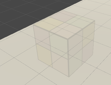
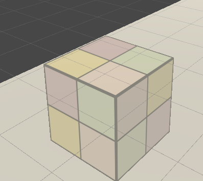
开启深度写入的半透明效果
解决物体排序错误的问题
我们可以使用两个pass来渲染模型,第一个pass开启深度写入,但不输出颜色,仅仅把该模型的深度值写入深度缓冲中。
Pass
{
	ZWrite On
	ColorMask 0
	//当 ColorMask设为0时,意味着该Pass不写入任何颜色通道(即不会输出任何颜色).
}
第二个pass进行正常的透明度混合。
ShaderLab的混合命令参数
参数
源颜色 (source color) :由片元着色器产生的颜色值,用S表示
目标颜色(destination color):指的是从颜色缓冲中读取到的颜色值,用D表示

第一个命令只提供了两个因子,这意味着将使用同样的混合因子来混合 RGB 通
道和 A 通道,即此时 SrcFactorA 将等千 SrcFactor, DstFactorA 将等于 DstFactor 。

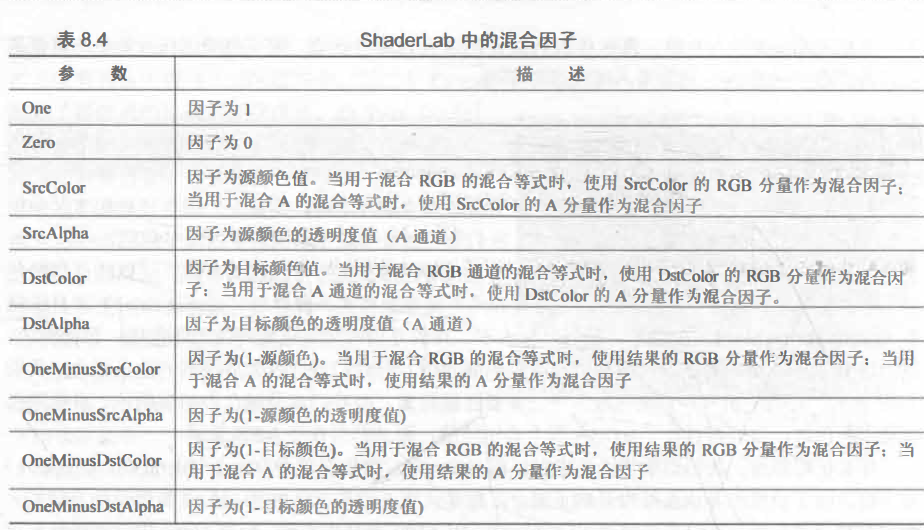
混合操作
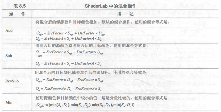

常见的混合类型
//正常(Normal), 即透明度混合
Blend SrcAlpha OneMinusSrcAlpha

//柔和相加(Soft Additive)
Blend OneMinusDstColor One

//正片叠底(Multiply), 即相乘
Blend DstColor Zero

//两倍相乘(2x Multiply)
Blend DstColor SrcColor

//变暗(Darken)
BlendOp Min
Blend One One

//变亮(Ligh七en)
BlendOp Max
Blend One One

//滤色(Screen)
Blend OneMinusDstColor One

//等同千
Blend One OneMinusSrcColor

//线性减淡(Linear Dodge)
Blend One One
双面透明的渲染
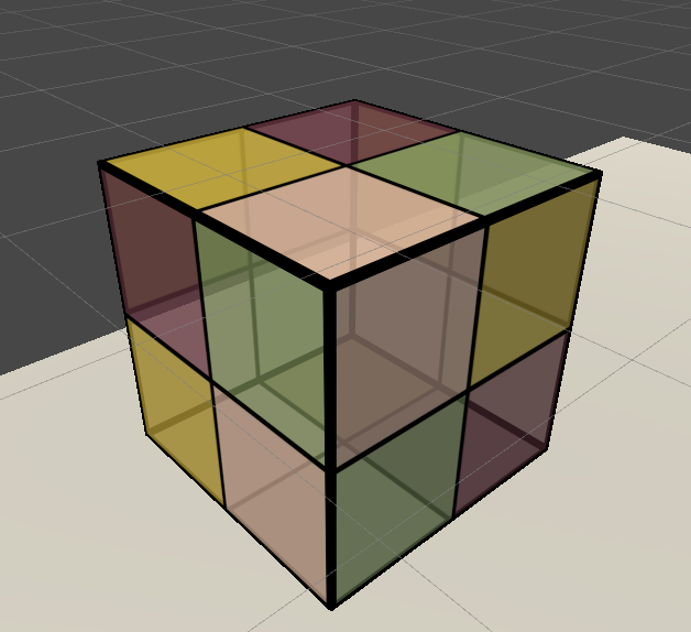
默认情况下渲染引擎剔除了物体背面的渲染图元。在这种情况下我们无法观察正方体背面的图元。
为了渲染顺序的正确性,我们把双面渲染工作分成两个Pass——第一个pass渲染背面,第二个Pass只渲染正面。
代码如下
Shader "Unity Shader Books/Chapter 8/Alpha Blend Both Sided"
{
    Properties
    {
        _Color ("Color Tint", Color) = (1, 1, 1, 1)
		_MainTex ("Main Tex", 2D) = "white" {}
        _AlphaScale("Alpha Scale",Range(0,1))=1
        //在透明纹理中控制整体的透明度

    }
    SubShader
    {
        Tags{"Queue"="Transparent" "IgnoreProjector"="True" "RenderType"="Transparent"}
        //透明度混合使用的标签是Transparent
        //RenderType标签把这个Shader归入到提前定义的组(这里就是Transparent组)中,指明该Shader是一个使用了透明度混合的Shader。
        Pass
        {
            Tags{"LightMode"="ForwardBase"}

            Cull Front
            ZWrite Off
            Blend SrcAlpha OneMinusSrcAlpha

            CGPROGRAM
            #pragma vertex vert
            #pragma fragment frag
            #include "Lighting.cginc"

            fixed4 _Color;
            sampler2D _MainTex;
            float4 _MainTex_ST;
            fixed _AlphaScale;

            struct a2v
            {
                float4 vertex:POSITION;
                float3 normal:NORMAL;
                float4 texcoord:TEXCOORD0;


            };

            struct v2f
            {
                float4 pos:SV_POSITION;
                float3 worldNormal:TEXCOORD0;
                float3 worldPos:TEXCOORD1;
                float2 uv:TEXCOORD2;
            };
            v2f vert(a2v v)
            {
                v2f o;
                o.pos = UnityObjectToClipPos(v.vertex);
                o.worldNormal = UnityObjectToWorldNormal(v.normal);
                o.worldPos=mul(unity_ObjectToWorld,v.vertex).xyz;
                o.uv=TRANSFORM_TEX(v.texcoord,_MainTex);
                return o;

            }
            fixed4 frag(v2f i):SV_Target
            {
                fixed3 worldNormal=normalize(i.worldNormal);
                fixed3 worldLightDir=normalize(UnityWorldSpaceLightDir(i.worldPos));
                fixed4 texColor=tex2D(_MainTex,i.uv);

                fixed3 albedo = texColor.rgb*_Color.rgb;
                fixed3 ambient=UNITY_LIGHTMODEL_AMBIENT.xyz*albedo;
                fixed3 diffuse=_LightColor0.rgb*albedo*max(0,dot(worldNormal,worldLightDir));
                return fixed4(ambient+diffuse,texColor.a*_AlphaScale);

            }
            ENDCG
        }
        Pass
        {
            Tags{"LightMode"="ForwardBase"}
            Cull Back
            ZWrite Off
            Blend SrcAlpha OneMinusSrcAlpha

            CGPROGRAM
            #pragma vertex vert
            #pragma fragment frag
            #include "Lighting.cginc"

            fixed4 _Color;
            sampler2D _MainTex;
            float4 _MainTex_ST;
            fixed _AlphaScale;

            struct a2v
            {
                float4 vertex:POSITION;
                float3 normal:NORMAL;
                float4 texcoord:TEXCOORD0;


            };

            struct v2f
            {
                float4 pos:SV_POSITION;
                float3 worldNormal:TEXCOORD0;
                float3 worldPos:TEXCOORD1;
                float2 uv:TEXCOORD2;
            };
            v2f vert(a2v v)
            {
                v2f o;
                o.pos = UnityObjectToClipPos(v.vertex);
                o.worldNormal = UnityObjectToWorldNormal(v.normal);
                o.worldPos=mul(unity_ObjectToWorld,v.vertex).xyz;
                o.uv=TRANSFORM_TEX(v.texcoord,_MainTex);
                return o;

            }
            fixed4 frag(v2f i):SV_Target
            {
                fixed3 worldNormal=normalize(i.worldNormal);
                fixed3 worldLightDir=normalize(UnityWorldSpaceLightDir(i.worldPos));
                fixed4 texColor=tex2D(_MainTex,i.uv);

                fixed3 albedo = texColor.rgb*_Color.rgb;
                fixed3 ambient=UNITY_LIGHTMODEL_AMBIENT.xyz*albedo;
                fixed3 diffuse=_LightColor0.rgb*albedo*max(0,dot(worldNormal,worldLightDir));
                return fixed4(ambient+diffuse,texColor.a*_AlphaScale);

            }
            ENDCG
        }
    }
    FallBack "Transparent/VertexLit"
}
两个Pass一样,只是第一个pass是 Cull Front
第二个Pass 是Cull Back
效果图:
中级篇
更复杂的光照
Unity的渲染路径

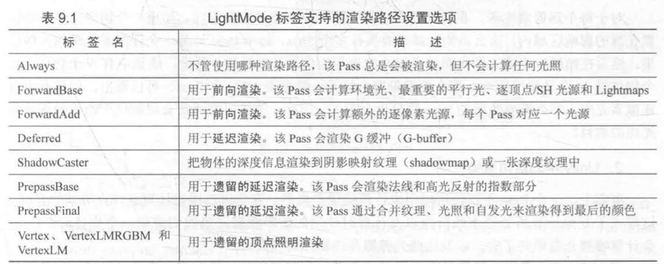
完成main camera的设置之后,我们就可以在Pass里的LightMode标签里面实现
例如:
Pass{
	Tags{"LightMode"="ForwardBase"}
}
其他标签:
1.前向渲染路径
在 Unity 中,前向渲染路径有 3 种处理光照(即照亮物体)的方式: 逐顶点处理 、逐像素处理,球谐函数 (Spherical Harmonics, SH) 处理 。
而决定一个光源使用哪种处理模式取决于它的类型和渲染模式。
光源类型指的是该光源是平行光还是其他类型的光源,
而光源的渲染模式指的是该光源是否是重要的 (Important)

如果光源被设置为Important,会按逐像素处理
Not Important的光源会按照逐顶点或者SH处理。
最亮的平行光总是按照逐像素处理的。
前向渲染的Pass
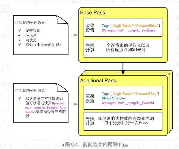
- Base Pass支持阴影,Additional Pass不支持阴影。
- 环境光和自发光也在Base Pass中计算
2.内置的光照变量和函数
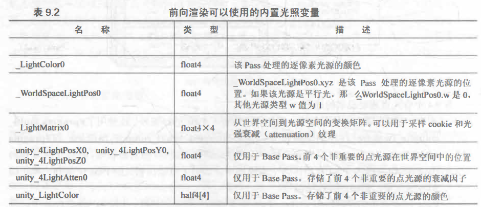
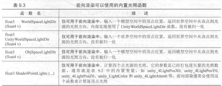
2.延迟渲染路径
除了前向渲染中使用的颜色缓冲和深度缓冲外,延迟渲染还会利用额外的缓冲区,这些缓冲区也被统称为 G 缓冲 ( G-buffer ), 其中 G 是英文 Geometry 的缩写。 G 缓冲区存储了我们所关心的表面(通常指的是离摄像机最近的表面)的其他信息,例如该表面的法线、位置、用于光照计算的材质属性等。
1.原理
主要包含了两个Pass,第一个Pass不进行光照计算,而是通过深度缓冲计算哪些片元是可见的。用于渲染G缓冲,在这个 Pass 中,我们会把物体的漫反射颜色、高光反射
颜色、平滑度 、法线、 自发光和深度等信息渲染到屏幕空间的 G 缓冲区中。对于每 个物体来说,这个 Pass仅 会执行一次。
在第二个Pass中我们利用 G 缓冲区的各个片元信息,例如表面法线、视角方向、漫反射系数等,进行真正的光照计算。
延迟渲染的效率与场景复杂度无关,而和我们使用的屏幕空间大小有关。
2.优点
对于延迟渲染路径来说,它最适合在场景中光源数目很多、如果使用前向渲染会造成性能瓶颈的情况下使用。而且,延迟渲染路径中的每个光源都可以按逐像素的方式处理。
3.缺点
- 不支持真正的抗锯齿
- 不能处理半透明物体
- 对显卡有要求
4.内置变量

Unity中的光源
面光源只能用于烘焙,使用范围狭窄。
实践:在前向渲染中处理不同的光源类型
代码:
// Upgrade NOTE: replaced '_LightMatrix0' with 'unity_WorldToLight'
// Upgrade NOTE: replaced 'mul(UNITY_MATRIX_MVP,*)' with 'UnityObjectToClipPos(*)'

Shader "Unity Shader Books/Chapter 9/Forward Rendering" {
	Properties {
		_Diffuse ("Diffuse", Color) = (1, 1, 1, 1)
		_Specular ("Specular", Color) = (1, 1, 1, 1)
		_Gloss ("Gloss", Range(8.0, 256)) = 20
	}
	SubShader {
		Tags { "RenderType"="Opaque" }

		Pass {
			// Pass for ambient light & first pixel light (directional light)
			Tags { "LightMode"="ForwardBase" }

			CGPROGRAM

			// Apparently need to add this declaration
			#pragma multi_compile_fwdbase
			//可以保证我们在Shader中使用光照衰减等光照变量可以被正确赋值

			#pragma vertex vert
			#pragma fragment frag

			#include "Lighting.cginc"

			fixed4 _Diffuse;
			fixed4 _Specular;
			float _Gloss;

			struct a2v {
				float4 vertex : POSITION;
				float3 normal : NORMAL;
			};

			struct v2f {
				float4 pos : SV_POSITION;
				float3 worldNormal : TEXCOORD0;
				float3 worldPos : TEXCOORD1;
			};

			v2f vert(a2v v) {
				v2f o;
				o.pos = UnityObjectToClipPos(v.vertex);

				o.worldNormal = UnityObjectToWorldNormal(v.normal);

				o.worldPos = mul(unity_ObjectToWorld, v.vertex).xyz;

				return o;
			}

			fixed4 frag(v2f i) : SV_Target {
				fixed3 worldNormal = normalize(i.worldNormal);
				fixed3 worldLightDir = normalize(_WorldSpaceLightPos0.xyz);
				//得到平行光的方向

				fixed3 ambient = UNITY_LIGHTMODEL_AMBIENT.xyz;

			 	fixed3 diffuse = _LightColor0.rgb * _Diffuse.rgb * max(0, dot(worldNormal, worldLightDir));
				//用——LightColor0来得到它的颜色和强度

			 	fixed3 viewDir = normalize(_WorldSpaceCameraPos.xyz - i.worldPos.xyz);
			 	fixed3 halfDir = normalize(worldLightDir + viewDir);
			 	fixed3 specular = _LightColor0.rgb * _Specular.rgb * pow(max(0, dot(worldNormal, halfDir)), _Gloss);

				fixed atten = 1.0;
				//衰减值为1就是没有衰减

				return fixed4(ambient + (diffuse + specular) * atten, 1.0);
			}

			ENDCG
		}

		Pass {
			// Pass for other pixel lights
			Tags { "LightMode"="ForwardAdd" }

			Blend One One

			CGPROGRAM

			// Apparently need to add this declaration
			#pragma multi_compile_fwdadd

			#pragma vertex vert
			#pragma fragment frag

			#include "Lighting.cginc"
			#include "AutoLight.cginc"

			fixed4 _Diffuse;
			fixed4 _Specular;
			float _Gloss;

			struct a2v {
				float4 vertex : POSITION;
				float3 normal : NORMAL;
			};

			struct v2f {
				float4 pos : SV_POSITION;
				float3 worldNormal : TEXCOORD0;
				float3 worldPos : TEXCOORD1;
			};

			v2f vert(a2v v) {
				v2f o;
				o.pos = UnityObjectToClipPos(v.vertex);

				o.worldNormal = UnityObjectToWorldNormal(v.normal);

				o.worldPos = mul(unity_ObjectToWorld, v.vertex).xyz;

				return o;
			}

			fixed4 frag(v2f i) : SV_Target {
				fixed3 worldNormal = normalize(i.worldNormal);
				#ifdef USING_DIRECTIONAL_LIGHT
					fixed3 worldLightDir = normalize(_WorldSpaceLightPos0.xyz);
				#else
					fixed3 worldLightDir = normalize(_WorldSpaceLightPos0.xyz - i.worldPos.xyz);
				#endif
				//如果是平行光,光源方向直接由_WorldSpaceLightPosO.xyz得到
				//如果是点光源或者聚光灯,_WorldSpaceLightPosO.xyz表示世界空间下的光源位置,减去顶点位置即可得到光源方向

				fixed3 diffuse = _LightColor0.rgb * _Diffuse.rgb * max(0, dot(worldNormal, worldLightDir));

				fixed3 viewDir = normalize(_WorldSpaceCameraPos.xyz - i.worldPos.xyz);
				fixed3 halfDir = normalize(worldLightDir + viewDir);
				fixed3 specular = _LightColor0.rgb * _Specular.rgb * pow(max(0, dot(worldNormal, halfDir)), _Gloss);

				#ifdef USING_DIRECTIONAL_LIGHT
					fixed atten = 1.0;
				#else
					#if defined (POINT)
				        float3 lightCoord = mul(unity_WorldToLight, float4(i.worldPos, 1)).xyz;
				        fixed atten = tex2D(_LightTexture0, dot(lightCoord, lightCoord).rr).UNITY_ATTEN_CHANNEL;
				    #elif defined (SPOT)
				        float4 lightCoord = mul(unity_WorldToLight, float4(i.worldPos, 1));
				        fixed atten = (lightCoord.z > 0) * tex2D(_LightTexture0, lightCoord.xy / lightCoord.w + 0.5).w * tex2D(_LightTextureB0, dot(lightCoord, lightCoord).rr).UNITY_ATTEN_CHANNEL;
				    #else
				        fixed atten = 1.0;
				    #endif
				#endif
				// 根据不同的光源类型处理衰减

				return fixed4((diffuse + specular) * atten, 1.0);
			}

			ENDCG
		}
	}
	FallBack "Specular"
}
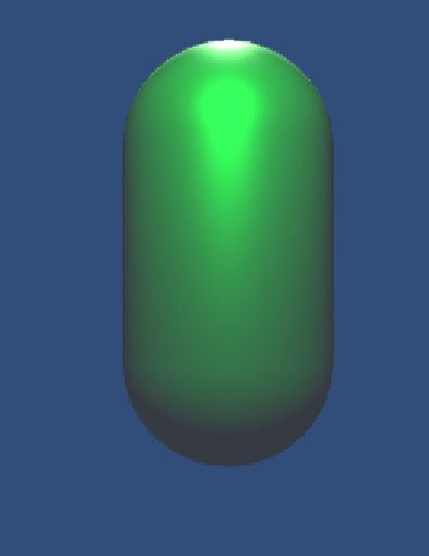
效果图:
光照衰减
1.用于光照衰减的纹理
Unity 在内部使用 一 张名为_LightTexture0的纹理来计算光源衰减。
为了对_LightTexture0 纹理采样得到给定点到该光源的衰减值,我们首先用变换矩阵 _LightMatrix0与顶点坐标相乘得到该点在光源空间中的位置。
float3 lightCoord = mul(_LightMatrixO, float4 (i.worldPosition, 1)).xyz;然后使用这个坐标的模的平方对纹理衰减采样,得到衰减值。
fixed atten = tex2D(_LightTextureO, dot(lightCoord, lightCoord).rr).UNITY_ATTEN_CHANNEL我们使用宏 UNITY_ATTEN_CHANNEL 来得到衰减纹理中衰减值所在的分量,以得到最终的衰减值.
阴影
实时渲染中,我们经常使用Shadow Map技术:把摄像机放到与光源重合的位置上,那么阴影区域就是摄像机看不到的区域。
在前向渲染路径中,如果场景中最重要的平行光开启了阴影, Unity 就会为该光源计算它的阴影映射纹理 (shadow map)。这张阴影映射纹理本质上也是一张深度图,它记录了从该光源的位置出发、能看到的场景中距离它最近的表面位置(深度信息)。
计算阴影映射纹理时,我们会使用ShadowCaster的Pass,从而得到深度信息。
如果我们想要一个物体接收来自其他物体的阴影,就必须在 Shader 中对阴影映射纹理(包括屏幕空间的阴影图)进行采样,把采样结果和最后的光照结果相乘来产生阴影效果。
如果我们想要一个物体向其他物体投射阴影,就必须把该物体加入到光源的阴影映射纹理的计算中,从而让其他物体在对阴影映射纹理采样时可以得到该物体的相关信息 。在 Unity中,这个过程是通过为该物体执行 LightMode 为 ShadowCaster 的 Pass 来实现的 。如果使用了屏幕空间的投影映射技术, Unity 还会使用这个 Pass 产生 一 张摄像机的深度纹理 。
2.不透明物体的阴影
ShadowCaster的Pass隐藏在了FallBack “Specular”里面,所以不需要我们手动实现
这是具体的实现:
Pass {
	Name "ShadowCaster"
	Tags { "LightMode" = "ShadowCaster" )
	CGPROGRAM
	#pragma vertex vert
	#pragma fragment frag
	#pragma multi_compile_shadowcas七er
	#include "UnityCG.cginc"
	struct v2f {
	V2F SHADOW CASTER;, .
	};
	v2f vert(appdata_base v)
	{
		v2f o;
		TRANSFER SHADOW CASTER NORMALOFFSET(o)
		return o;
	}
	float4 frag(v2f i) : SV_Target
	{
		SHADOW_CASTER_FRAGMENT(i)
	}
	ENDCG
}
让物体投射与接收阴影:
// Upgrade NOTE: replaced '_LightMatrix0' with 'unity_WorldToLight'
// Upgrade NOTE: replaced 'mul(UNITY_MATRIX_MVP,*)' with 'UnityObjectToClipPos(*)'

Shader "Unity Shader Books/Chapter 9/Shadow" {
	Properties {
		_Diffuse ("Diffuse", Color) = (1, 1, 1, 1)
		_Specular ("Specular", Color) = (1, 1, 1, 1)
		_Gloss ("Gloss", Range(8.0, 256)) = 20
	}
	SubShader {
		Tags { "RenderType"="Opaque" }

		Pass {
			// Pass for ambient light & first pixel light (directional light)
			Tags { "LightMode"="ForwardBase" }

			CGPROGRAM

			// Apparently need to add this declaration
			#pragma multi_compile_fwdbase
			//可以保证我们在Shader中使用光照衰减等光照变量可以被正确赋值

			#pragma vertex vert
			#pragma fragment frag

			#include "Lighting.cginc"
			#include "AutoLight.cginc"

			fixed4 _Diffuse;
			fixed4 _Specular;
			float _Gloss;

			struct a2v {
				float4 vertex : POSITION;
				float3 normal : NORMAL;
			};

			struct v2f {
				float4 pos : SV_POSITION;
				float3 worldNormal : TEXCOORD0;
				float3 worldPos : TEXCOORD1;
				SHADOW_COORDS(2)
				//声明一个对阴影纹理采样的坐标,参数时下一个可用寄存器的索引值。

			};

			v2f vert(a2v v) {
				v2f o;
				o.pos = UnityObjectToClipPos(v.vertex);

				o.worldNormal = UnityObjectToWorldNormal(v.normal);

				o.worldPos = mul(unity_ObjectToWorld, v.vertex).xyz;
				TRANSFER_SHADOW(o)
				return o;
			}

			fixed4 frag(v2f i) : SV_Target {
				fixed3 worldNormal = normalize(i.worldNormal);
				fixed3 worldLightDir = normalize(_WorldSpaceLightPos0.xyz);
				//得到平行光的方向

				fixed3 ambient = UNITY_LIGHTMODEL_AMBIENT.xyz;

			 	fixed3 diffuse = _LightColor0.rgb * _Diffuse.rgb * max(0, dot(worldNormal, worldLightDir));
				//用——LightColor0来得到它的颜色和强度

			 	fixed3 viewDir = normalize(_WorldSpaceCameraPos.xyz - i.worldPos.xyz);
			 	fixed3 halfDir = normalize(worldLightDir + viewDir);
			 	fixed3 specular = _LightColor0.rgb * _Specular.rgb * pow(max(0, dot(worldNormal, halfDir)), _Gloss);

				fixed atten = 1.0;
				//衰减值为1就是没有衰减

				fixed shadow=SHADOW_ATTENUATION(i);
				//负责使用_ShadowCoord对相关的纹理进行采样,得到阴影信息。

				return fixed4(ambient + (diffuse + specular) * atten*shadow, 1.0);
			}

			ENDCG
		}

		Pass {
			// Pass for other pixel lights
			Tags { "LightMode"="ForwardAdd" }

			Blend One One

			CGPROGRAM

			// Apparently need to add this declaration
			#pragma multi_compile_fwdadd

			#pragma vertex vert
			#pragma fragment frag

			#include "Lighting.cginc"
			#include "AutoLight.cginc"

			fixed4 _Diffuse;
			fixed4 _Specular;
			float _Gloss;

			struct a2v {
				float4 vertex : POSITION;
				float3 normal : NORMAL;
			};

			struct v2f {
				float4 pos : SV_POSITION;
				float3 worldNormal : TEXCOORD0;
				float3 worldPos : TEXCOORD1;
			};

			v2f vert(a2v v) {
				v2f o;
				o.pos = UnityObjectToClipPos(v.vertex);

				o.worldNormal = UnityObjectToWorldNormal(v.normal);

				o.worldPos = mul(unity_ObjectToWorld, v.vertex).xyz;

				return o;
			}

			fixed4 frag(v2f i) : SV_Target {
				fixed3 worldNormal = normalize(i.worldNormal);
				#ifdef USING_DIRECTIONAL_LIGHT
					fixed3 worldLightDir = normalize(_WorldSpaceLightPos0.xyz);
				#else
					fixed3 worldLightDir = normalize(_WorldSpaceLightPos0.xyz - i.worldPos.xyz);
				#endif
				//如果是平行光,光源方向直接由_WorldSpaceLightPosO.xyz得到
				//如果是点光源或者聚光灯,_WorldSpaceLightPosO.xyz表示世界空间下的光源位置,减去顶点位置即可得到光源方向

				fixed3 diffuse = _LightColor0.rgb * _Diffuse.rgb * max(0, dot(worldNormal, worldLightDir));

				fixed3 viewDir = normalize(_WorldSpaceCameraPos.xyz - i.worldPos.xyz);
				fixed3 halfDir = normalize(worldLightDir + viewDir);
				fixed3 specular = _LightColor0.rgb * _Specular.rgb * pow(max(0, dot(worldNormal, halfDir)), _Gloss);

				#ifdef USING_DIRECTIONAL_LIGHT
					fixed atten = 1.0;
				#else
					#if defined (POINT)
				        float3 lightCoord = mul(unity_WorldToLight, float4(i.worldPos, 1)).xyz;
				        fixed atten = tex2D(_LightTexture0, dot(lightCoord, lightCoord).rr).UNITY_ATTEN_CHANNEL;
				    #elif defined (SPOT)
				        float4 lightCoord = mul(unity_WorldToLight, float4(i.worldPos, 1));
				        fixed atten = (lightCoord.z > 0) * tex2D(_LightTexture0, lightCoord.xy / lightCoord.w + 0.5).w * tex2D(_LightTextureB0, dot(lightCoord, lightCoord).rr).UNITY_ATTEN_CHANNEL;
				    #else
				        fixed atten = 1.0;
				    #endif
				#endif
				// 根据不同的光源类型处理衰减

				return fixed4((diffuse + specular) * atten, 1.0);
			}

			ENDCG
		}
	}
	FallBack "Specular"
}
统一管理光照衰减与阴影
代码如下:
// Upgrade NOTE: replaced '_LightMatrix0' with 'unity_WorldToLight'
// Upgrade NOTE: replaced 'mul(UNITY_MATRIX_MVP,*)' with 'UnityObjectToClipPos(*)'

Shader "Unity Shader Books/Chapter 9/Attenuation And Shadow" {
	Properties {
		_Diffuse ("Diffuse", Color) = (1, 1, 1, 1)
		_Specular ("Specular", Color) = (1, 1, 1, 1)
		_Gloss ("Gloss", Range(8.0, 256)) = 20
	}
	SubShader {
		Tags { "RenderType"="Opaque" }

		Pass {
			// Pass for ambient light & first pixel light (directional light)
			Tags { "LightMode"="ForwardBase" }

			CGPROGRAM

			// Apparently need to add this declaration
			#pragma multi_compile_fwdbase
			//可以保证我们在Shader中使用光照衰减等光照变量可以被正确赋值

			#pragma vertex vert
			#pragma fragment frag

			#include "Lighting.cginc"
			#include "AutoLight.cginc"

			fixed4 _Diffuse;
			fixed4 _Specular;
			float _Gloss;

			struct a2v {
				float4 vertex : POSITION;
				float3 normal : NORMAL;
			};

			struct v2f {
				float4 pos : SV_POSITION;
				float3 worldNormal : TEXCOORD0;
				float3 worldPos : TEXCOORD1;
				SHADOW_COORDS(2)
				//声明一个对阴影纹理采样的坐标,参数时下一个可用寄存器的索引值。

			};

			v2f vert(a2v v) {
				v2f o;
				o.pos = UnityObjectToClipPos(v.vertex);

				o.worldNormal = UnityObjectToWorldNormal(v.normal);

				o.worldPos = mul(unity_ObjectToWorld, v.vertex).xyz;
				TRANSFER_SHADOW(o)
				return o;
			}

			fixed4 frag(v2f i) : SV_Target {
				fixed3 worldNormal = normalize(i.worldNormal);
				fixed3 worldLightDir = normalize(_WorldSpaceLightPos0.xyz);
				//得到平行光的方向

				fixed3 ambient = UNITY_LIGHTMODEL_AMBIENT.xyz;

			 	fixed3 diffuse = _LightColor0.rgb * _Diffuse.rgb * max(0, dot(worldNormal, worldLightDir));
				//用——LightColor0来得到它的颜色和强度

			 	fixed3 viewDir = normalize(_WorldSpaceCameraPos.xyz - i.worldPos.xyz);
			 	fixed3 halfDir = normalize(worldLightDir + viewDir);
			 	fixed3 specular = _LightColor0.rgb * _Specular.rgb * pow(max(0, dot(worldNormal, halfDir)), _Gloss);

				UNITY_LIGHT_ATTENUATION(atten,i,i.worldPos);
				//将光照衰减与阴影值相乘后的结果存储在第一个参数中

				return fixed4(ambient + (diffuse + specular) * atten, 1.0);
			}

			ENDCG
		}

		Pass {
			// Pass for other pixel lights
			Tags { "LightMode"="ForwardAdd" }

			Blend One One

			CGPROGRAM

			// Apparently need to add this declaration
			#pragma multi_compile_fwdadd

			#pragma vertex vert
			#pragma fragment frag

			#include "Lighting.cginc"
			#include "AutoLight.cginc"

			fixed4 _Diffuse;
			fixed4 _Specular;
			float _Gloss;

			struct a2v {
				float4 vertex : POSITION;
				float3 normal : NORMAL;
			};

			struct v2f {
				float4 pos : SV_POSITION;
				float3 worldNormal : TEXCOORD0;
				float3 worldPos : TEXCOORD1;
			};

			v2f vert(a2v v) {
				v2f o;
				o.pos = UnityObjectToClipPos(v.vertex);

				o.worldNormal = UnityObjectToWorldNormal(v.normal);

				o.worldPos = mul(unity_ObjectToWorld, v.vertex).xyz;

				return o;
			}

			fixed4 frag(v2f i) : SV_Target {
				fixed3 worldNormal = normalize(i.worldNormal);
				#ifdef USING_DIRECTIONAL_LIGHT
					fixed3 worldLightDir = normalize(_WorldSpaceLightPos0.xyz);
				#else
					fixed3 worldLightDir = normalize(_WorldSpaceLightPos0.xyz - i.worldPos.xyz);
				#endif
				//如果是平行光,光源方向直接由_WorldSpaceLightPosO.xyz得到
				//如果是点光源或者聚光灯,_WorldSpaceLightPosO.xyz表示世界空间下的光源位置,减去顶点位置即可得到光源方向

				fixed3 diffuse = _LightColor0.rgb * _Diffuse.rgb * max(0, dot(worldNormal, worldLightDir));

				fixed3 viewDir = normalize(_WorldSpaceCameraPos.xyz - i.worldPos.xyz);
				fixed3 halfDir = normalize(worldLightDir + viewDir);
				fixed3 specular = _LightColor0.rgb * _Specular.rgb * pow(max(0, dot(worldNormal, halfDir)), _Gloss);

				#ifdef USING_DIRECTIONAL_LIGHT
					fixed atten = 1.0;
				#else
					#if defined (POINT)
				        float3 lightCoord = mul(unity_WorldToLight, float4(i.worldPos, 1)).xyz;
				        fixed atten = tex2D(_LightTexture0, dot(lightCoord, lightCoord).rr).UNITY_ATTEN_CHANNEL;
				    #elif defined (SPOT)
				        float4 lightCoord = mul(unity_WorldToLight, float4(i.worldPos, 1));
				        fixed atten = (lightCoord.z > 0) * tex2D(_LightTexture0, lightCoord.xy / lightCoord.w + 0.5).w * tex2D(_LightTextureB0, dot(lightCoord, lightCoord).rr).UNITY_ATTEN_CHANNEL;
				    #else
				        fixed atten = 1.0;
				    #endif
				#endif
				// 根据不同的光源类型处理衰减

				return fixed4((diffuse + specular) * atten, 1.0);
			}

			ENDCG
		}
	}
	FallBack "Specular"
}
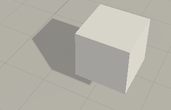
效果图:
透明度物体的阴影
代码如下:
Shader "Unity Shader Books/Chapter 9/Alpha Test With Shadow"
{
    Properties
    {
        _Color ("Color Tint", Color) = (1, 1, 1, 1)
		_MainTex ("Main Tex", 2D) = "white" {}
        _Cutoff("Alpha Cutoff",Range(0,1))=0.5
        //用于决定调用clip进行透明度测试的判断条件,范围是[0,1],因为纹理像素就是再此范围内

    }
    SubShader
    {
        Tags{"Queue"="AlphaTest" "IgnoreProjector"="True" "RenderType"="TransparentCutout"}
        //使用了透明度测试的Shader都应该在SubShader里面设置这三个标签
        //把 Queue 标 签设置为 AlphaTest
        //RenderType常被用于着色器替换功能,把Shader归到提前定义的组,指明该Shader是用了透明度测试的Shader
        //把IgnoreProjector设置为True,这意味着这个Shader不会受到投影器 (Projectors) 的影响。

        Pass
        {
            Tags{"LightMode"="ForwardBase"}
            CGPROGRAM
            #pragma vertex vert
            #pragma fragment frag
            #include "Lighting.cginc"
            #include "AutoLight.cginc"

            fixed4 _Color;
            sampler2D _MainTex;
            float4 _MainTex_ST;
            fixed4 _Cutoff;

            struct a2v
            {
                float4 vertex:POSITION;
                float3 normal:NORMAL;
                float4 texcoord:TEXCOORD0;


            };

            struct v2f
            {
                float4 pos:SV_POSITION;
                float3 worldNormal:TEXCOORD0;
                float3 worldPos:TEXCOORD1;
                float2 uv:TEXCOORD2;
                SHADOW_COORDS(3)
            };
            v2f vert(a2v v)
            {
                v2f o;
                o.pos = UnityObjectToClipPos(v.vertex);
                o.worldNormal = UnityObjectToWorldNormal(v.normal);
                o.worldPos=mul(unity_ObjectToWorld,v.vertex).xyz;
                o.uv=TRANSFORM_TEX(v.texcoord,_MainTex);
                TRANSFER_SHADOW(o);
                return o;

            }
            fixed4 frag(v2f i):SV_Target
            {
                fixed3 worldNormal=normalize(i.worldNormal);
                fixed3 worldLightDir=normalize(UnityWorldSpaceLightDir(i.worldPos));
                fixed4 texColor=tex2D(_MainTex,i.uv);
                clip(texColor.a-_Cutoff);
                fixed3 albedo = texColor.rgb*_Color.rgb;
                fixed3 ambient=UNITY_LIGHTMODEL_AMBIENT.xyz*albedo;
                fixed3 diffuse=_LightColor0.rgb*albedo*max(0,dot(worldNormal,worldLightDir));
                UNITY_LIGHT_ATTENUATION(atten,i,i.worldPos);
                return fixed4(ambient+diffuse*atten,1.0);

            }
            ENDCG
        }
    }
    FallBack "Transparent/Cutout/VertexLit"
}
效果图:
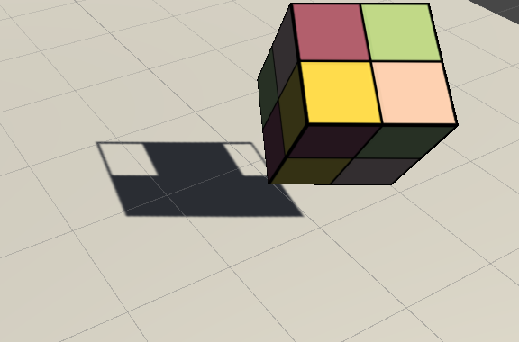
高级纹理
1.立方体纹理(Cubemap)
立方体纹理是环境映射的一种实现方法。
优点:简单快速,得到的效果好。
缺点:场景改变后就需要重新生成立方体纹理,不能模拟多次反射的结果。
1.天空盒
新建材质后,Shader选择Skybox/6 Sided。赋值六张图,即可得到正常的天空盒。
2.用于环境映射
创建环境映射的三种方法;
1.由特殊布局的纹理创建。(把Texture Type设置为Cubemap)
链接:https://docs.unity3d.com/Manual/class-Cubemap.html
2.手动创建Cubemap,再把六张图赋给它。
3.由脚本生成。
链接:https://docs.unity3d.com/ScriptReference/Camera.RenderToCubemap.html
3.反射
代码如下:
Shader "Unity Shader Books/Chapter 10/Reflection"
{
    Properties
    {
        _Color ("Color Tint", Color) = (1,1,1,1)
        _ReflectColor("Reflection Color",Color)=(1,1,1,1)
        _ReflectAmount("Reflect Amount",Range(0,1))=1
        _Cubemap("Reflect Cubemap",Cube)="_Skybox"{}
    }
    SubShader {
		Tags { "RenderType"="Opaque" "Queue"="Geometry"}

		Pass {
			Tags { "LightMode"="ForwardBase" }

			CGPROGRAM

			#pragma multi_compile_fwdbase

			#pragma vertex vert
			#pragma fragment frag

			#include "Lighting.cginc"
			#include "AutoLight.cginc"

			fixed4 _Color;
			fixed4 _ReflectColor;
			fixed _ReflectAmount;
			samplerCUBE _Cubemap;

			struct a2v {
				float4 vertex : POSITION;
				float3 normal : NORMAL;
			};

			struct v2f {
				float4 pos : SV_POSITION;
				float3 worldPos : TEXCOORD0;
				fixed3 worldNormal : TEXCOORD1;
				fixed3 worldViewDir : TEXCOORD2;
				fixed3 worldRefl : TEXCOORD3;
				SHADOW_COORDS(4)
			};

			v2f vert(a2v v) {
				v2f o;

				o.pos = UnityObjectToClipPos(v.vertex);

				o.worldNormal = UnityObjectToWorldNormal(v.normal);

				o.worldPos = mul(unity_ObjectToWorld, v.vertex).xyz;

				o.worldViewDir = UnityWorldSpaceViewDir(o.worldPos);


				o.worldRefl = reflect(-o.worldViewDir, o.worldNormal);
				//根据反射方向求逆得到入射方向

				TRANSFER_SHADOW(o);

				return o;
			}

			fixed4 frag(v2f i) : SV_Target {
				fixed3 worldNormal = normalize(i.worldNormal);
				fixed3 worldLightDir = normalize(UnityWorldSpaceLightDir(i.worldPos));
				fixed3 worldViewDir = normalize(i.worldViewDir);

				fixed3 ambient = UNITY_LIGHTMODEL_AMBIENT.xyz;

				fixed3 diffuse = _LightColor0.rgb * _Color.rgb * max(0, dot(worldNormal, worldLightDir));

				// Use the reflect dir in world space to access the cubemap
				fixed3 reflection = texCUBE(_Cubemap, i.worldRefl).rgb * _ReflectColor.rgb;
				//对立方体纹理采样

				UNITY_LIGHT_ATTENUATION(atten, i, i.worldPos);

				// Mix the diffuse color with the reflected color
				fixed3 color = ambient + lerp(diffuse, reflection, _ReflectAmount) * atten;

				return fixed4(color, 1.0);
			}

			ENDCG
		}
    }
    FallBack "Reflective/VertixLit"
}
效果图:
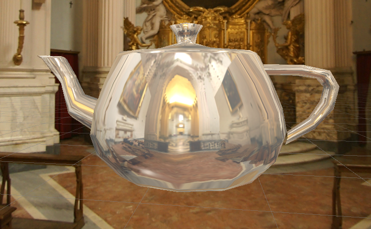
4.折射
公式:

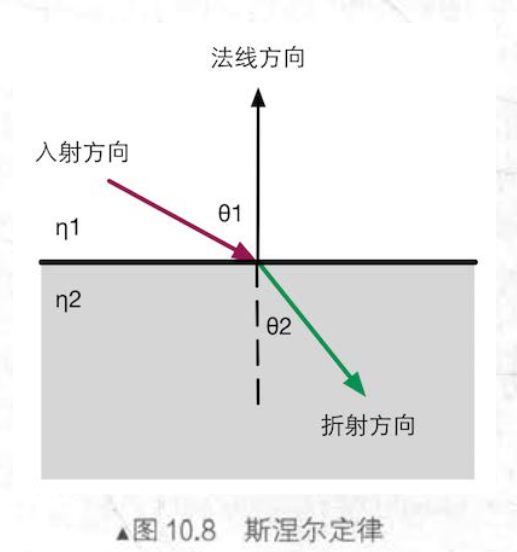
代码如下:
Shader "Unity Shader Books/Chapter 10/Refraction"
{
    Properties {
		_Color ("Color Tint", Color) = (1, 1, 1, 1)
		_RefractColor ("Refraction Color", Color) = (1, 1, 1, 1)
		_RefractAmount ("Refraction Amount", Range(0, 1)) = 1
		_RefractRatio ("Refraction Ratio", Range(0.1, 1)) = 0.5
    	//使用该属性得到不同的透射比,用来计算折射方向
		_Cubemap ("Refraction Cubemap", Cube) = "_Skybox" {}
	}
	SubShader {
		Tags { "RenderType"="Opaque" "Queue"="Geometry"}

		Pass {
			Tags { "LightMode"="ForwardBase" }

			CGPROGRAM

			#pragma multi_compile_fwdbase

			#pragma vertex vert
			#pragma fragment frag

			#include "Lighting.cginc"
			#include "AutoLight.cginc"

			fixed4 _Color;
			fixed4 _RefractColor;
			float _RefractAmount;
			fixed _RefractRatio;
			samplerCUBE _Cubemap;

			struct a2v {
				float4 vertex : POSITION;
				float3 normal : NORMAL;
			};

			struct v2f {
				float4 pos : SV_POSITION;
				float3 worldPos : TEXCOORD0;
				fixed3 worldNormal : TEXCOORD1;
				fixed3 worldViewDir : TEXCOORD2;
				fixed3 worldRefr : TEXCOORD3;
				SHADOW_COORDS(4)
			};

			v2f vert(a2v v) {
				v2f o;
				o.pos = UnityObjectToClipPos(v.vertex);

				o.worldNormal = UnityObjectToWorldNormal(v.normal);

				o.worldPos = mul(unity_ObjectToWorld, v.vertex).xyz;

				o.worldViewDir = UnityWorldSpaceViewDir(o.worldPos);

				// Compute the refract dir in world space
				o.worldRefr = refract(-normalize(o.worldViewDir), normalize(o.worldNormal), _RefractRatio);
				//使用refract来计算折射方向
				//第一个参数是入射光线的方向(必须是归一化的)
				//第二个参数是表面法线(归一化的)
				//第三个参数是入射光线所在介质的折射率和折射光线所在介质的折射率之间的比值
				//函数返回值就是计算得到的折射方向
				TRANSFER_SHADOW(o);

				return o;
			}

			fixed4 frag(v2f i) : SV_Target {
				fixed3 worldNormal = normalize(i.worldNormal);
				fixed3 worldLightDir = normalize(UnityWorldSpaceLightDir(i.worldPos));
				fixed3 worldViewDir = normalize(i.worldViewDir);

				fixed3 ambient = UNITY_LIGHTMODEL_AMBIENT.xyz;

				fixed3 diffuse = _LightColor0.rgb * _Color.rgb * max(0, dot(worldNormal, worldLightDir));

				// Use the refract dir in world space to access the cubemap
				fixed3 refraction = texCUBE(_Cubemap, i.worldRefr).rgb * _RefractColor.rgb;

				UNITY_LIGHT_ATTENUATION(atten, i, i.worldPos);

				// Mix the diffuse color with the refract color
				fixed3 color = ambient + lerp(diffuse, refraction, _RefractAmount) * atten;

				return fixed4(color, 1.0);
			}

			ENDCG
		}
	}
	FallBack "Reflective/VertexLit"
}
效果图:
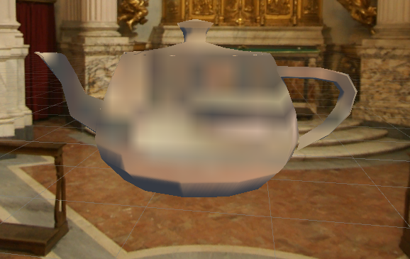
5.菲涅尔反射
菲涅尔反射是一种光学现象:当你站在湖边,直接低头看脚边的水面时,你会发现水几乎是透明的,你可以直接看到水底的小鱼和石子;但是,当你抬头看远处 的水面时,会发现几乎看不到水下的情景 ,而只能看到水面反射的环境 。
公式:
Schlick菲涅尔近似等式:

Empricial 菲涅耳近似等式:

代码如下:
// Upgrade NOTE: replaced '_Object2World' with 'unity_ObjectToWorld'
// Upgrade NOTE: replaced 'mul(UNITY_MATRIX_MVP,*)' with 'UnityObjectToClipPos(*)'

Shader "Unity Shaders Book/Chapter 10/Fresnel" {
	Properties {
		_Color ("Color Tint", Color) = (1, 1, 1, 1)
		_FresnelScale ("Fresnel Scale", Range(0, 1)) = 0.5
		_Cubemap ("Reflection Cubemap", Cube) = "_Skybox" {}
	}
	SubShader {
		Tags { "RenderType"="Opaque" "Queue"="Geometry"}

		Pass {
			Tags { "LightMode"="ForwardBase" }

			CGPROGRAM

			#pragma multi_compile_fwdbase

			#pragma vertex vert
			#pragma fragment frag

			#include "Lighting.cginc"
			#include "AutoLight.cginc"

			fixed4 _Color;
			fixed _FresnelScale;
			samplerCUBE _Cubemap;

			struct a2v {
				float4 vertex : POSITION;
				float3 normal : NORMAL;
			};

			struct v2f {
				float4 pos : SV_POSITION;
				float3 worldPos : TEXCOORD0;
  				fixed3 worldNormal : TEXCOORD1;
  				fixed3 worldViewDir : TEXCOORD2;
  				fixed3 worldRefl : TEXCOORD3;
 	 			SHADOW_COORDS(4)
			};

			v2f vert(a2v v) {
				v2f o;
				o.pos = UnityObjectToClipPos(v.vertex);

				o.worldNormal = UnityObjectToWorldNormal(v.normal);

				o.worldPos = mul(unity_ObjectToWorld, v.vertex).xyz;

				o.worldViewDir = UnityWorldSpaceViewDir(o.worldPos);

				o.worldRefl = reflect(-o.worldViewDir, o.worldNormal);

				TRANSFER_SHADOW(o);

				return o;
			}

			fixed4 frag(v2f i) : SV_Target {
				fixed3 worldNormal = normalize(i.worldNormal);
				fixed3 worldLightDir = normalize(UnityWorldSpaceLightDir(i.worldPos));
				fixed3 worldViewDir = normalize(i.worldViewDir);

				fixed3 ambient = UNITY_LIGHTMODEL_AMBIENT.xyz;

				UNITY_LIGHT_ATTENUATION(atten, i, i.worldPos);

				fixed3 reflection = texCUBE(_Cubemap, i.worldRefl).rgb;

				fixed fresnel = _FresnelScale + (1 - _FresnelScale) * pow(1 - dot(worldViewDir, worldNormal), 5);

				fixed3 diffuse = _LightColor0.rgb * _Color.rgb * max(0, dot(worldNormal, worldLightDir));

				fixed3 color = ambient + lerp(diffuse, reflection, saturate(fresnel)) * atten;

				return fixed4(color, 1.0);
			}

			ENDCG
		}
	}
	FallBack "Reflective/VertexLit"
}
效果图:
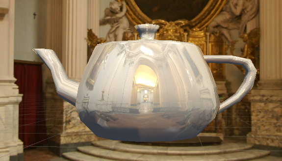
2.渲染纹理
现代GPU可以把三维场景渲染到一个中间缓冲中,即渲染目标纹理,而不是传统帧缓冲或后备缓冲。Unity为渲染目标纹理单独定义了一种纹理类型–渲染纹理(Render Texture)
1.镜面效果
使用摄像机捕捉画面,并渲染到材质中。
代码如下:
// Upgrade NOTE: replaced 'mul(UNITY_MATRIX_MVP,*)' with 'UnityObjectToClipPos(*)'

Shader "Unity Shaders Book/Chapter 10/Mirror" {
	Properties {
		_MainTex ("Main Tex", 2D) = "white" {}
	}
	SubShader {
		Tags { "RenderType"="Opaque" "Queue"="Geometry"}

		Pass {
			CGPROGRAM

			#pragma vertex vert
			#pragma fragment frag

			sampler2D _MainTex;

			struct a2v {
				float4 vertex : POSITION;
				float3 texcoord : TEXCOORD0;
			};

			struct v2f {
				float4 pos : SV_POSITION;
				float2 uv : TEXCOORD0;
			};

			v2f vert(a2v v) {
				v2f o;
				o.pos = UnityObjectToClipPos(v.vertex);

				o.uv = v.texcoord;
				// Mirror needs to filp x
				o.uv.x = 1 - o.uv.x;

				return o;
			}

			fixed4 frag(v2f i) : SV_Target {
				return tex2D(_MainTex, i.uv);
			}

			ENDCG
		}
	}
 	FallBack Off
}
效果图:
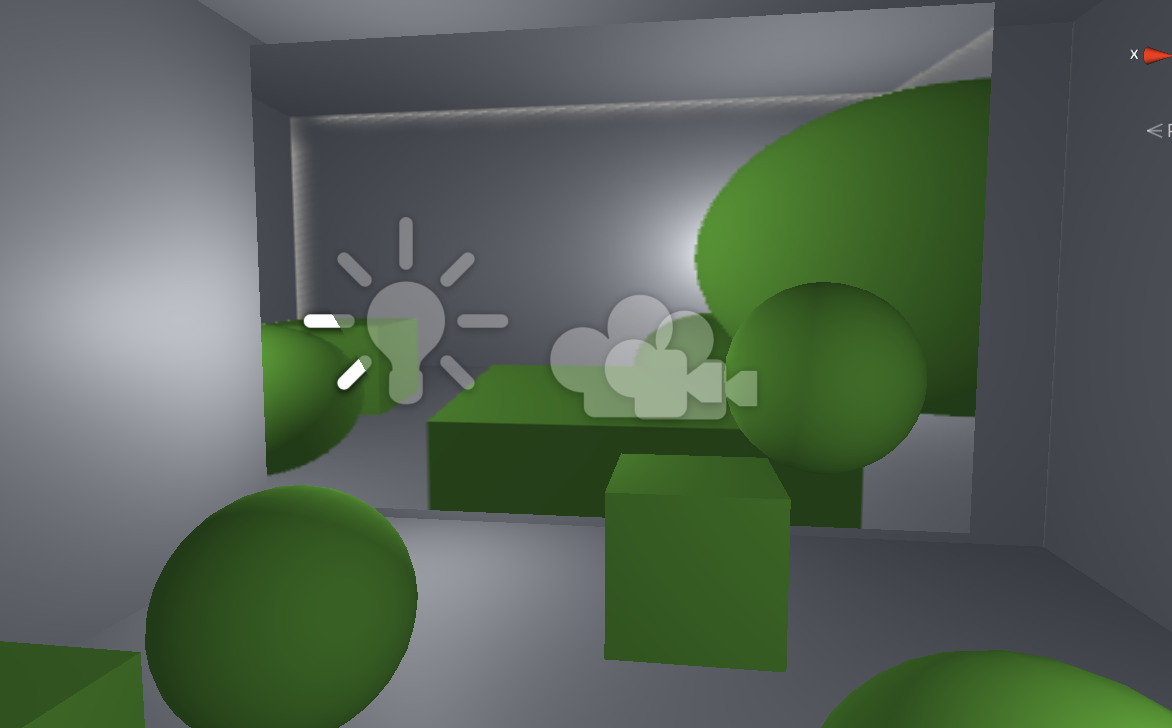
2.玻璃效果(GrabPass)
代码如下:
// Upgrade NOTE: replaced '_Object2World' with 'unity_ObjectToWorld'
// Upgrade NOTE: replaced 'mul(UNITY_MATRIX_MVP,*)' with 'UnityObjectToClipPos(*)'

Shader "Unity Shader Books/Chapter 10/Glass Refraction" {
	Properties {
		_MainTex ("Main Tex", 2D) = "white" {}
		_BumpMap ("Normal Map", 2D) = "bump" {}
		_Cubemap ("Environment Cubemap", Cube) = "_Skybox" {}
		//模拟反射的环境纹理
		_Distortion ("Distortion", Range(0, 100)) = 10
		//控制模拟折射时图像扭曲程度
		_RefractAmount ("Refract Amount", Range(0.0, 1.0)) = 1.0
		//控制折射程度
	}
	SubShader {
		// We must be transparent, so other objects are drawn before this one.
		Tags { "Queue"="Transparent" "RenderType"="Opaque" }
		//把 Queue设置成 Transparent 可以确保该物体渲染时,其他所有不透明物体都已经被渲染到屏幕上了
		// This pass grabs the screen behind the object into a texture.
		// We can access the result in the next pass as _RefractionTex
		GrabPass { "_RefractionTex" }
		//通过关键词 GrabPass定义了一个抓取屏幕图像的 Pass,在这个 Pass 中我们定义了一个字符串,该字符串内部的名称决定了抓取得到的屏幕图像将会被存入哪个纹理中。

		Pass {
			CGPROGRAM

			#pragma vertex vert
			#pragma fragment frag

			#include "UnityCG.cginc"

			sampler2D _MainTex;
			float4 _MainTex_ST;
			sampler2D _BumpMap;
			float4 _BumpMap_ST;
			samplerCUBE _Cubemap;
			float _Distortion;
			fixed _RefractAmount;
			sampler2D _RefractionTex;
			float4 _RefractionTex_TexelSize;
			//得到纹理的纹素大小

			struct a2v {
				float4 vertex : POSITION;
				float3 normal : NORMAL;
				float4 tangent : TANGENT;
				float2 texcoord: TEXCOORD0;
			};

			struct v2f {
				float4 pos : SV_POSITION;
				float4 scrPos : TEXCOORD0;
				float4 uv : TEXCOORD1;
				float4 TtoW0 : TEXCOORD2;
			    float4 TtoW1 : TEXCOORD3;
			    float4 TtoW2 : TEXCOORD4;
			};

			v2f vert (a2v v) {
				v2f o;
				o.pos = UnityObjectToClipPos(v.vertex);

				o.scrPos = ComputeGrabScreenPos(o.pos);
				//得到对应被抓取的屏幕空间的采样坐标
				o.uv.xy = TRANSFORM_TEX(v.texcoord, _MainTex);
				o.uv.zw = TRANSFORM_TEX(v.texcoord, _BumpMap);

				float3 worldPos = mul(unity_ObjectToWorld, v.vertex).xyz;
				fixed3 worldNormal = UnityObjectToWorldNormal(v.normal);
				fixed3 worldTangent = UnityObjectToWorldDir(v.tangent.xyz);
				fixed3 worldBinormal = cross(worldNormal, worldTangent) * v.tangent.w;

				o.TtoW0 = float4(worldTangent.x, worldBinormal.x, worldNormal.x, worldPos.x);
				o.TtoW1 = float4(worldTangent.y, worldBinormal.y, worldNormal.y, worldPos.y);
				o.TtoW2 = float4(worldTangent.z, worldBinormal.z, worldNormal.z, worldPos.z);
				//x,y,z对应了切线,副切线和法线的方向
				return o;
			}

			fixed4 frag (v2f i) : SV_Target {
				float3 worldPos = float3(i.TtoW0.w, i.TtoW1.w, i.TtoW2.w);
				fixed3 worldViewDir = normalize(UnityWorldSpaceViewDir(worldPos));

				// Get the normal in tangent space
				fixed3 bump = UnpackNormal(tex2D(_BumpMap, i.uv.zw));

				// Compute the offset in tangent space
				float2 offset = bump.xy * _Distortion * _RefractionTex_TexelSize.xy;
				i.scrPos.xy = offset * i.scrPos.z + i.scrPos.xy;
				fixed3 refrCol = tex2D(_RefractionTex, i.scrPos.xy/i.scrPos.w).rgb;

				// Convert the normal to world space
				bump = normalize(half3(dot(i.TtoW0.xyz, bump), dot(i.TtoW1.xyz, bump), dot(i.TtoW2.xyz, bump)));
				fixed3 reflDir = reflect(-worldViewDir, bump);
				fixed4 texColor = tex2D(_MainTex, i.uv.xy);
				fixed3 reflCol = texCUBE(_Cubemap, reflDir).rgb * texColor.rgb;

				fixed3 finalColor = reflCol * (1 - _RefractAmount) + refrCol * _RefractAmount;

				return fixed4(finalColor, 1);
			}

			ENDCG
		}
	}

	FallBack "Diffuse"
}
效果图:
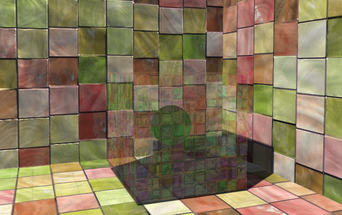
3.程序纹理
由计算机脚本生成图像,然后再绘制出来。
cs代码例子:
using System;
using System.Collections;
using System.Collections.Generic;
using UnityEngine;

[ExecuteInEditMode]//让脚本可以在编辑器模式下运行
public class ProceduralTextureGeneration : MonoBehaviour
{
    public Material material = null;

    private Texture2D m_generatedTexture;
    #region Material properties

    [SerializeField,SetProperty("textureWidth")]
    private int m_textureWidth = 512;
    public int textureWidth
    {
        get { return m_textureWidth;}
        set
        {
            m_textureWidth = value;
            _UpdateMaterial();
        }
    }

    [SerializeField,SetProperty("backgroundColor")]//为了在面板修改属性时可以执行set函数
    private Color m_backgroundColor=Color.white;
    public Color BackgroundColor
    {
        get
        {
            return m_backgroundColor;
        }
        set
        {
            m_backgroundColor = value;
            _UpdateMaterial();
        }
    }

    [SerializeField,SetProperty("circleColor")]
    private Color m_circleColor=Color.yellow;
    public Color circleColor
    {
        get { return m_circleColor;}
        set
        {
            m_circleColor = value;
            _UpdateMaterial();
        }
    }

    [SerializeField, SetProperty("blurFactoe")]
    private float m_blurFactor = 2.0f;
    public float blurFactor
    {
        get
        {
            return m_blurFactor;
        }
        set
        {
            m_blurFactor = value;
            _UpdateMaterial();
        }
    }

    #endregion

    private void Start()
    {
        if (material==null)
        {
            Renderer renderer = gameObject.GetComponent<Renderer>();
            if (renderer == null)
            {
                Debug.Log("Can't find a renderer");
                return;
            }

            material = renderer.sharedMaterial;

        }
        _UpdateMaterial();
    }

    private void _UpdateMaterial()
    {
        if (material!=null)
        {
            m_generatedTexture = _GenerateProceduralTexture();
            material.SetTexture("_MainTex",m_generatedTexture);
        }
    }

    private Texture2D _GenerateProceduralTexture()
    {
        Texture2D proceduralTexture = new Texture2D(textureWidth, textureWidth);
        float circleInterval = textureWidth / 4.0f;
        float radius = textureWidth / 10.0f;
        float edgeBlur = 1.0f / blurFactor;
        for (int w = 0; w < textureWidth; w++)
        {
            for (int h = 0; h < textureWidth; h++)
            {
                Color pixel = BackgroundColor;
                for (int i = 0; i < 3; i++)
                {
                    for (int j = 0; j < 3; j++)
                    {
                        Vector2 circleCenter = new Vector2(circleInterval * (i + 1), circleInterval * (j + 1));
                        float dist = Vector2.Distance(new Vector2(w, h), circleCenter) - radius;
                        Color color = _MixColor(circleColor, new Color(pixel.r, pixel.g, pixel.b, 0.0f),
                            Mathf.SmoothStep(0f, 1.0f, dist * edgeBlur));
                        pixel = _MixColor(pixel, color, color.a);

                    }
                }
                proceduralTexture.SetPixel(w,h,pixel);
            }
        }
        proceduralTexture.Apply();
        return proceduralTexture;
    }
    private Color _MixColor(Color color0, Color color1, float mixFactor) {
        Color mixColor = Color.white;
        mixColor.r = Mathf.Lerp(color0.r, color1.r, mixFactor);
        mixColor.g = Mathf.Lerp(color0.g, color1.g, mixFactor);
        mixColor.b = Mathf.Lerp(color0.b, color1.b, mixFactor);
        mixColor.a = Mathf.Lerp(color0.a, color1.a, mixFactor);
        return mixColor;
    }
}
效果图:
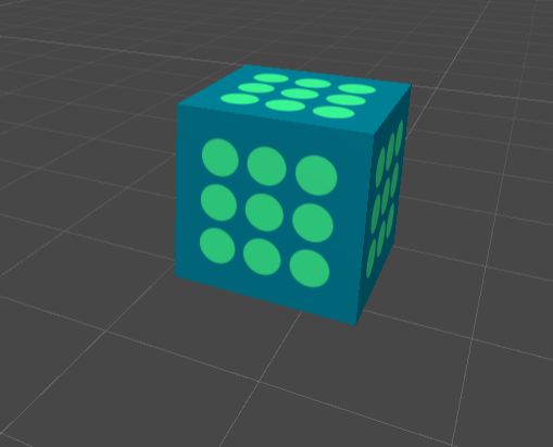
让画面动起来
1.内置时间变量

2.纹理动画
1.序列帧动画
代码如下:
Shader "Unity Shader Books/Chapter 11/Image Sequence Animation"
{
    Properties
    {
        _Color ("Color Tint", Color) = (1,1,1,1)
        _MainTex ("Image Sequence", 2D) = "white" {}
        _HorizontalAmount("Horizontal Amount",Float)=4
        _VerticalAmount("Vertical Amount",Float)=4
        //水平方向和竖直方向包含关键帧的个数
        _Speed("Speed",Range(1,100))=30

    }
    SubShader
    {
        Tags{"Queue"="Transparent" "IgnoreProjects"="True" "RenderType"="Transparent"}
        Pass
        {
            Tags{"LightMode"="ForwardBase"}
            ZWrite Off
            Blend SrcAlpha OneMinusSrcAlpha
            //使用半透明的标配来设置Tags
            CGPROGRAM
            #pragma vertex vert
			#pragma fragment frag

			#include "UnityCG.cginc"

			fixed4 _Color;
			sampler2D _MainTex;
			float4 _MainTex_ST;
			float _HorizontalAmount;
			float _VerticalAmount;
			float _Speed;

			struct a2v {
			    float4 vertex : POSITION;
			    float2 texcoord : TEXCOORD0;
			};

			struct v2f {
			    float4 pos : SV_POSITION;
			    float2 uv : TEXCOORD0;
			};
            v2f vert(a2v v)
            {
	            v2f o;
            	o.pos = UnityObjectToClipPos(v.vertex);
            	o.uv=TRANSFORM_TEX(v.texcoord,_MainTex);
            	return o;

            }
            fixed4 frag(v2f i):SV_Target
            {
            	float time=floor(_Time.y*_Speed);
            	//_Time.y 就是自该场景加载后所经过的时间,与speed相乘得到模拟的时间
            	float row=floor(time/_HorizontalAmount);
            	//行索引
            	float column=time-row*_HorizontalAmount;
            	//列索引
            	half2 uv=i.uv+half2(column,-row);
            	//把原纹理坐标 i.uv按行数和列数进行等分, 得到每个子图像的纹理坐标范围。、
            	//竖直偏移要用减法
            	uv.x/=_HorizontalAmount;
            	uv.y/=_VerticalAmount;
            	//用当前的行列数对结果进行偏移
            	float4 c=tex2D(_MainTex,uv);
            	c.rgb*=_Color;
            	return c;
            }
            ENDCG
        }
    }

    FallBack "Transparent/VertexLit"
}
效果图:
2.背景滚动
代码如下:
Shader "Unity Shader Books/Chapter 11/Scrolling Background"
{
    Properties
    {
        _MainTex ("Base Layer(RGB)", 2D) = "white" {}
        _DetailTex("2nd Layer(RGB)",2D)="white"{}
        _ScrollX("Base layer Scroll Speed",Float)=1.0
        _ScrollY("2nd layer Scroll Speed",Float)=1.0
        _Multiplier("Layer Multiplier",Float)=1
    }
    SubShader
    {
        Tags { "RenderType"="Opaque" "Queue"="Geometry"}

		Pass {
			Tags { "LightMode"="ForwardBase" }

			CGPROGRAM

			#pragma vertex vert
			#pragma fragment frag

			#include "UnityCG.cginc"

			sampler2D _MainTex;
			sampler2D _DetailTex;
			float4 _MainTex_ST;
			float4 _DetailTex_ST;
			float _ScrollX;
			float _Scroll2X;
			float _Multiplier;

			struct a2v {
				float4 vertex : POSITION;
				float4 texcoord : TEXCOORD0;
			};

			struct v2f {
				float4 pos : SV_POSITION;
				float4 uv : TEXCOORD0;
			};

			v2f vert (a2v v) {
				v2f o;
				o.pos = UnityObjectToClipPos(v.vertex);

				o.uv.xy = TRANSFORM_TEX(v.texcoord, _MainTex) + frac(float2(_ScrollX, 0.0) * _Time.y);
				o.uv.zw = TRANSFORM_TEX(v.texcoord, _DetailTex) + frac(float2(_Scroll2X, 0.0) * _Time.y);
				//利用 TRANSFORM_TEX 来得到初始的纹理坐标。
				//利用内置的 _Time.y 变量在水平方向上对纹理坐标进行偏移,以此达到滚动的效果。
				return o;
			}

			fixed4 frag (v2f i) : SV_Target {
				fixed4 firstLayer = tex2D(_MainTex, i.uv.xy);
				fixed4 secondLayer = tex2D(_DetailTex, i.uv.zw);

				fixed4 c = lerp(firstLayer, secondLayer, secondLayer.a);
				//使用第二层纹理的透明通道来混合两张纹理
				c.rgb *= _Multiplier;

				return c;
			}

			ENDCG
		}
    }
    FallBack "VertexLit"
}
效果图:
3.顶点动画
1.河流
代码如下:
Shader "Unity Shader Books/Chapter 11/Water"
{
    Properties
    {
        _Color ("Color Tint", Color) = (1,1,1,1)
        _MainTex ("Main Tex", 2D) = "white" {}
        _Magnitude("Distortion Magnitude",Float)=1
    	//偏移量
        _Frequency("Distortion Frequency",Float)=1
        _InvWaveLength("Distortion Inverse Wave Length",Float)=10
        _Speed("Speed",Float)=0.5
    }
    SubShader {
		// Need to disable batching because of the vertex animation
		Tags {"Queue"="Transparent" "IgnoreProjector"="True" "RenderType"="Transparent" "DisableBatching"="True"}
    	//DisableBatching指明是否需要批处理

		Pass {
			Tags { "LightMode"="ForwardBase" }

			ZWrite Off
			Blend SrcAlpha OneMinusSrcAlpha
			Cull Off

			CGPROGRAM
			#pragma vertex vert
			#pragma fragment frag

			#include "UnityCG.cginc"

			sampler2D _MainTex;
			float4 _MainTex_ST;
			fixed4 _Color;
			float _Magnitude;
			float _Frequency;
			float _InvWaveLength;
			float _Speed;

			struct a2v {
				float4 vertex : POSITION;
				float4 texcoord : TEXCOORD0;
			};

			struct v2f {
				float4 pos : SV_POSITION;
				float2 uv : TEXCOORD0;
			};

			v2f vert(a2v v) {
				v2f o;

				float4 offset;
				offset.yzw = float3(0.0, 0.0, 0.0);
				offset.x = sin(_Frequency * _Time.y + v.vertex.x * _InvWaveLength + v.vertex.y * _InvWaveLength + v.vertex.z * _InvWaveLength) * _Magnitude;
				o.pos = UnityObjectToClipPos(v.vertex + offset);
				//利用 _Frequency 属性和内 置的 _Time.y 变墓来控制正弦函数的频率

				o.uv = TRANSFORM_TEX(v.texcoord, _MainTex);
				o.uv +=  float2(0.0, _Time.y * _Speed);

				return o;
			}

			fixed4 frag(v2f i) : SV_Target {
				fixed4 c = tex2D(_MainTex, i.uv);
				c.rgb *= _Color.rgb;

				return c;
			}

			ENDCG
		}
	}
	FallBack "Transparent/VertexLit"
}
效果图:
2.广告牌技术
会根据视角方向来旋转多边形,使多边形看起来总是面对摄像机。
代码如下:
// Upgrade NOTE: replaced '_World2Object' with 'unity_WorldToObject'
// Upgrade NOTE: replaced 'mul(UNITY_MATRIX_MVP,*)' with 'UnityObjectToClipPos(*)'

Shader "Unity Shader Books/Chapter 11/Billboard"
{
	Properties {
		_MainTex ("Main Tex", 2D) = "white" {}
		_Color ("Color Tint", Color) = (1, 1, 1, 1)
		_VerticalBillboarding ("Vertical Restraints", Range(0, 1)) = 1
		//用于调整是固定法线还是固定指向上的方向,即约束垂直方向的程度。
	}
	SubShader {
		// Need to disable batching because of the vertex animation
		Tags {"Queue"="Transparent" "IgnoreProjector"="True" "RenderType"="Transparent" "DisableBatching"="True"}

		Pass {
			Tags { "LightMode"="ForwardBase" }

			ZWrite Off
			Blend SrcAlpha OneMinusSrcAlpha
			Cull Off

			CGPROGRAM

			#pragma vertex vert
			#pragma fragment frag

			#include "Lighting.cginc"

			sampler2D _MainTex;
			float4 _MainTex_ST;
			fixed4 _Color;
			fixed _VerticalBillboarding;

			struct a2v {
				float4 vertex : POSITION;
				float4 texcoord : TEXCOORD0;
			};

			struct v2f {
				float4 pos : SV_POSITION;
				float2 uv : TEXCOORD0;
			};

			v2f vert (a2v v) {
				v2f o;

				// Suppose the center in object space is fixed
				float3 center = float3(0, 0, 0);
				float3 viewer = mul(unity_WorldToObject,float4(_WorldSpaceCameraPos, 1));

				float3 normalDir = viewer - center;
				// If _VerticalBillboarding equals 1, we use the desired view dir as the normal dir
				// Which means the normal dir is fixed
				// Or if _VerticalBillboarding equals 0, the y of normal is 0
				// Which means the up dir is fixed
				normalDir.y =normalDir.y * _VerticalBillboarding;
				normalDir = normalize(normalDir);
				// Get the approximate up dir
				// If normal dir is already towards up, then the up dir is towards front
				float3 upDir = abs(normalDir.y) > 0.999 ? float3(0, 0, 1) : float3(0, 1, 0);
				float3 rightDir = normalize(cross(upDir, normalDir));
				upDir = normalize(cross(normalDir, rightDir));
				//得到了三个正交基矢量

				// Use the three vectors to rotate the quad
				float3 centerOffs = v.vertex.xyz - center;
				float3 localPos = center + rightDir * centerOffs.x + upDir * centerOffs.y + normalDir * centerOffs.z;

				o.pos = UnityObjectToClipPos(float4(localPos, 1));
				o.uv = TRANSFORM_TEX(v.texcoord,_MainTex);

				return o;
			}

			fixed4 frag (v2f i) : SV_Target {
				fixed4 c = tex2D (_MainTex, i.uv);
				c.rgb *= _Color.rgb;

				return c;
			}

			ENDCG
		}
	}
	FallBack "Transparent/VertexLit"
}
效果图:
高级篇
1.屏幕后处理
1.基类
我们可以使用OnRenderImage函数来获取当前屏幕的渲染纹理。然后调用Graphics.Blit函数来处理图像。
2.对比度
cs脚本代码如下(挂在摄像机上):
using System.Collections;
using System.Collections.Generic;
using UnityEngine;

public class BrightnessSaturationAndContrast : PostEffectsBase
{
    public Shader briSatConShader;
    private Material briSatMaterial;

    public Material material
    {
        get
        {
            briSatMaterial = CheckShaderAndCreateMaterial(briSatConShader, briSatMaterial);
            return briSatMaterial;
        }

    }

    [Range(0.0f, 3.0f)] public float brightness = 1.0f;
    [Range(0, 3)] public float saturation = 1.0f;
    [Range(0f, 3f)] public float contrast = 1.0f;

    void OnRenderImage(RenderTexture src, RenderTexture dest)
    {
        if (material!=null)
        {
            material.SetFloat("_Brigthness",brightness);
            material.SetFloat("_Stauration",saturation);
            material.SetFloat("_Contrast",contrast);
            Graphics.Blit(src,dest,material);

        }
        else
        {
            Graphics.Blit(src,dest);
        }
    }
}
Shader代码:
// Upgrade NOTE: replaced 'mul(UNITY_MATRIX_MVP,*)' with 'UnityObjectToClipPos(*)'

Shader "Unity Shader Books/Chapter 12/Brightness Saturation And Contrast" {
	Properties {
		_MainTex ("Base (RGB)", 2D) = "white" {}
		_Brightness ("Brightness", Float) = 1
		_Saturation("Saturation", Float) = 1
		_Contrast("Contrast", Float) = 1
	}
	SubShader {
		Pass {
			ZTest Always Cull Off ZWrite Off

			CGPROGRAM
			#pragma vertex vert
			#pragma fragment frag

			#include "UnityCG.cginc"

			sampler2D _MainTex;
			half _Brightness;
			half _Saturation;
			half _Contrast;

			struct v2f {
				float4 pos : SV_POSITION;
				half2 uv: TEXCOORD0;
			};

			v2f vert(appdata_img v) {
				v2f o;

				o.pos = UnityObjectToClipPos(v.vertex);

				o.uv = v.texcoord;

				return o;
			}

			fixed4 frag(v2f i) : SV_Target {
				fixed4 renderTex = tex2D(_MainTex, i.uv);
				//对原屏幕采样

				// Apply brightness
				fixed3 finalColor = renderTex.rgb * _Brightness;

				// Apply saturation
				fixed luminance = 0.2125 * renderTex.r + 0.7154 * renderTex.g + 0.0721 * renderTex.b;
				fixed3 luminanceColor = fixed3(luminance, luminance, luminance);
				finalColor = lerp(luminanceColor, finalColor, _Saturation);
				//插值得到希望的饱和度颜色
				// Apply contrast
				fixed3 avgColor = fixed3(0.5, 0.5, 0.5);
				finalColor = lerp(avgColor, finalColor, _Contrast);

				return fixed4(finalColor, renderTex.a);
			}

			ENDCG
		}
	}

	Fallback Off
}
3.边缘检测
1.卷积
卷积操作就是使用一个卷积核 (kernel) 对一张图像中的每个像素进行一系列操作。

2.边缘检测的算子
相邻像素之间的差值可以用梯度来表示,边缘处的梯度自然比较大。
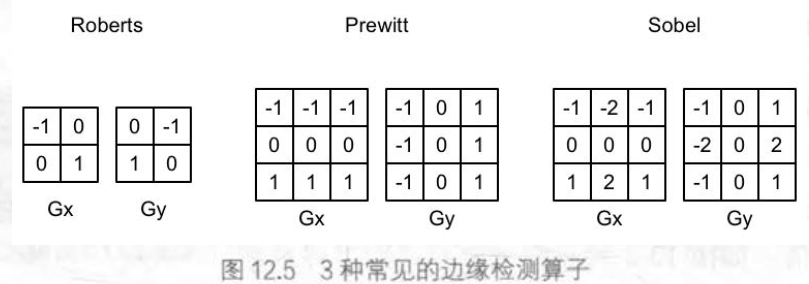
在进行边缘检测时,我们需要对每个像素分别进行一次卷积计算,得到两个方向上的梯度值 Gx 和 Gy, 而整体的梯度可按下面的公式计算而得:
$$
G=/G_x/+/G_y/
$$
3.实践
cs代码:
using System;
using System.Collections;
using System.Collections.Generic;
using UnityEngine;

public class EdgeDetection : PostEffectsBase
{
    public Shader edgeDetectShader;
    private Material edgeDetectMaterial=null;

    public Material material
    {
        get
        {
            edgeDetectMaterial = CheckShaderAndCreateMaterial(edgeDetectShader, edgeDetectMaterial);
            return edgeDetectMaterial;
        }
    }

    [Range(0, 1)] public float edgesOnly = 0.0f;
    public Color edgeColor = Color.black;
    public Color backgroundColor=Color.white;

    private void OnRenderImage(RenderTexture src, RenderTexture dest)
    {
        if (material!=null)
        {
            material.SetFloat("_EdgeOnly",edgesOnly);
            material.SetColor("_EdgeColor",edgeColor);
            material.SetColor("_BackgroundColor",backgroundColor);
            Graphics.Blit(src,dest,material);

        }
        else
        {
            Graphics.Blit(src,dest);
        }
    }
}
Shader代码:
// Upgrade NOTE: replaced 'mul(UNITY_MATRIX_MVP,*)' with 'UnityObjectToClipPos(*)'

Shader "Unity Shaders Book/Chapter 12/Edge Detection" {
	Properties {
		_MainTex ("Base (RGB)", 2D) = "white" {}
		_EdgeOnly ("Edge Only", Float) = 1.0
		_EdgeColor ("Edge Color", Color) = (0, 0, 0, 1)
		_BackgroundColor ("Background Color", Color) = (1, 1, 1, 1)
	}
	SubShader {
		Pass {
			ZTest Always Cull Off ZWrite Off

			CGPROGRAM

			#include "UnityCG.cginc"

			#pragma vertex vert
			#pragma fragment fragSobel

			sampler2D _MainTex;
			uniform half4 _MainTex_TexelSize;
			fixed _EdgeOnly;
			fixed4 _EdgeColor;
			fixed4 _BackgroundColor;

			struct v2f {
				float4 pos : SV_POSITION;
				half2 uv[9] : TEXCOORD0;
			};

			v2f vert(appdata_img v) {
				v2f o;
				o.pos = UnityObjectToClipPos(v.vertex);

				half2 uv = v.texcoord;

				o.uv[0] = uv + _MainTex_TexelSize.xy * half2(-1, -1);
				o.uv[1] = uv + _MainTex_TexelSize.xy * half2(0, -1);
				o.uv[2] = uv + _MainTex_TexelSize.xy * half2(1, -1);
				o.uv[3] = uv + _MainTex_TexelSize.xy * half2(-1, 0);
				o.uv[4] = uv + _MainTex_TexelSize.xy * half2(0, 0);
				o.uv[5] = uv + _MainTex_TexelSize.xy * half2(1, 0);
				o.uv[6] = uv + _MainTex_TexelSize.xy * half2(-1, 1);
				o.uv[7] = uv + _MainTex_TexelSize.xy * half2(0, 1);
				o.uv[8] = uv + _MainTex_TexelSize.xy * half2(1, 1);
				//在 v2 f 结构体中定义了一 个 维数为 9 的纹理数组,对应了使用 Sobel 算子采样时需要的9个邻域纹理坐标。
				return o;
			}

			fixed luminance(fixed4 color) {
				return  0.2125 * color.r + 0.7154 * color.g + 0.0721 * color.b;
			}

			half Sobel(v2f i) {
				const half Gx[9] = {-1,  0,  1,
										-2,  0,  2,
										-1,  0,  1};
				const half Gy[9] = {-1, -2, -1,
										0,  0,  0,
										1,  2,  1};

				half texColor;
				half edgeX = 0;
				half edgeY = 0;
				for (int it = 0; it < 9; it++) {
					texColor = luminance(tex2D(_MainTex, i.uv[it]));
					edgeX += texColor * Gx[it];
					edgeY += texColor * Gy[it];
				}

				half edge = 1 - abs(edgeX) - abs(edgeY);

				return edge;
			}

			fixed4 fragSobel(v2f i) : SV_Target {
				half edge = Sobel(i);

				fixed4 withEdgeColor = lerp(_EdgeColor, tex2D(_MainTex, i.uv[4]), edge);
				fixed4 onlyEdgeColor = lerp(_EdgeColor, _BackgroundColor, edge);
				return lerp(withEdgeColor, onlyEdgeColor, _EdgeOnly);
				//调用 Sobel 函数计算当前像素的梯度值 edge , 并利用该值分别计算了背景为原图和纯色下的颜色值 , 然后利用 _E dgeOnly 在两者之间插值得到最终的像素值。
 			}

			ENDCG
		}
	}
	FallBack Off
}
效果图:
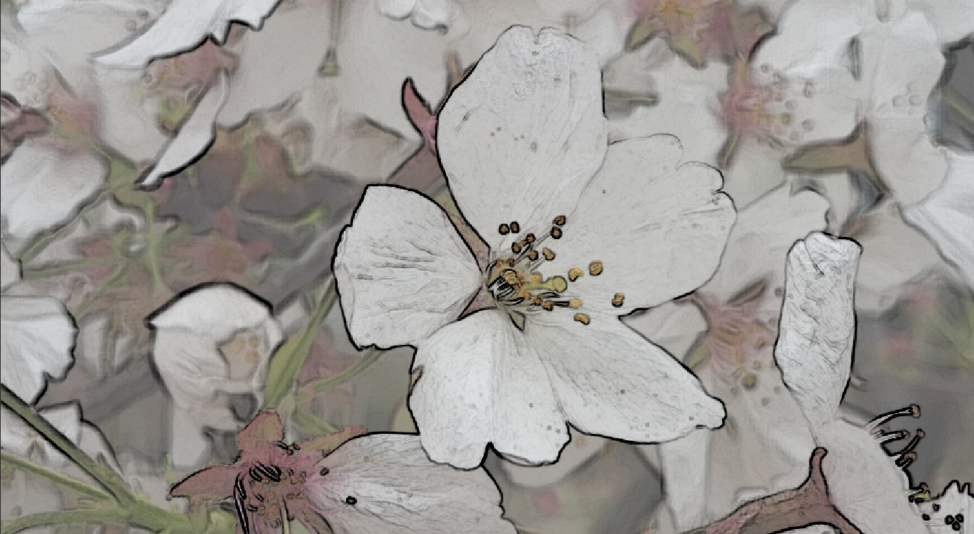
4.高斯模糊
均值模糊:使用了卷积操作,它使用的卷积核中的各个元素值都相等,且相加等于
1, 也就是说,卷积后得到的像素值是其邻域内各个像素值的平均值。
中值模糊:选择邻域内对所有像素排序后的中值替换掉原颜色。
高斯模糊:同样利用了卷积计算 ,它使用的卷积核名为高斯核 。高斯核是 一 个正方形大小的滤波核,其中每个元素的计算都是基于下面的高斯方程:

o是标准方差,一般取1,x,y对应了当前位置到卷积核中心的整数距离。
高斯方程很好地模拟了邻域每个像 素对当前处理像素的影响程度——距离越近 ,影响越大。高斯核的维数越高,模糊程度越大。
cs代码如下:
using System;
using System.Collections;
using System.Collections.Generic;
using UnityEngine;

public class GsussianBlur : PostEffectsBase
{
    public Shader gaussianBlurShader;
    private Material gaussianBlurMaterial;

    public Material material
    {
        get
        {
            gaussianBlurMaterial = CheckShaderAndCreateMaterial(gaussianBlurShader, gaussianBlurMaterial);
            return gaussianBlurMaterial;

        }
    }

    [Range(0, 4)] public int iterations = 3;
    [Range(0.2f, 3f)] public float blurSpread = 0.6f;
    //_BlurSize 越大,模糊程度越高 , 但采样数却不会受到影响。但过大的 _BlurSize 值会造成虚影 ,
    [Range(1, 8)] public int downSample = 2;
    //而 downSample 越大 , 需要 处 理的像素数越少,同时也能进一步提高模糊程度,但过大会导致图像像素化

    private void OnRenderImage(RenderTexture src, RenderTexture dest)
    {
        if (material!=null)
        {
            int rtW = src.width / downSample;
            int rtH = src.height / downSample;
            RenderTexture buffer0=RenderTexture.GetTemporary(rtW,rtH,0);
            //利用RenderTexture.GetTemporary函数分配了一块与屏幕图像大小相同的缓冲区。
            buffer0.filterMode = FilterMode.Bilinear;
            Graphics.Blit(src,buffer0);
            for (int i = 0; i < iterations; i++)
            {
                material.SetFloat("_BlurSize",1.0f+i*blurSpread);
                RenderTexture buffer1=RenderTexture.GetTemporary(rtW,rtH,0);
                Graphics.Blit(buffer0,buffer1,material,0);
                RenderTexture.ReleaseTemporary(buffer0);
                //调用 RenderTexture . ReleaseTemporary 来释放之前分 配 的缓存。
                buffer0 = buffer1;
                buffer1=RenderTexture.GetTemporary(rtW,rtH,0);
                Graphics.Blit(buffer0,buffer1,material,1);
                RenderTexture.ReleaseTemporary(buffer0);
                buffer0 = buffer1;
            }
            Graphics.Blit(buffer0,dest);
            RenderTexture.ReleaseTemporary(buffer0);

        }
        else
        {
            Graphics.Blit(src,dest);
        }
    }
}
Shader代码:
Shader "Unity Shader Books/Chapter 12/Gaussian Blur"
{
    Properties
    {
        _MainTex("Base (RGB)",2D)="whiet"{}
        _BlurSize("Blur Size",Float)=1.0

    }
    SubShader
    {
        CGINCLUDE
        #include "UnityCG.cginc"

        sampler2D _MainTex;
        half4 _MainTex_TexelSize;
        float _BlurSize;

        struct v2f
        {
            float4 pos:SV_POSITION;
            half2 uv[5]:TEXCOORD0;

        };
        v2f vertBlurVertical(appdata_img v)
        {
            v2f o;
            o.pos=UnityObjectToClipPos(v.vertex);
            half2 uv=v.texcoord;
            o.uv[0]=uv;
            o.uv[1]=uv+float2(0.0,_MainTex_TexelSize.y*1.0)*_BlurSize;
            o.uv[2]=uv-float2(0.0,_MainTex_TexelSize.y*1.0)*_BlurSize;
            o.uv[3]=uv+float2(0.0,_MainTex_TexelSize.y*2.0)*_BlurSize;
            o.uv[4]=uv-float2(0.0,_MainTex_TexelSize.y*2.0)*_BlurSize;
            return o;

        }
        fixed4 fragBlur(v2f i):SV_Target
        {
            float weight[3]={0.4026,0.2442,0.0545};
            fixed3 sum=tex2D(_MainTex,i.uv[0]).rgb*weight[0];
            for (int it = 1; it < 3; it++) {
				sum += tex2D(_MainTex, i.uv[it*2-1]).rgb * weight[it];
				sum += tex2D(_MainTex, i.uv[it*2]).rgb * weight[it];
			}
            return fixed4(sum,1.0);
        }
        ENDCG
        ZTest Always Cull Off ZWrite Off
        Pass
        {
            NAME "GAUSSIAN_BLUR_VERYICAL"
            CGPROGRAM
            #pragma vertex vertBlurVertical
            #pragma fragment fragBlur

            ENDCG
        }
        Pass
        {
            NAME "GAUSSIAN_BLUR_HORIZONTAL"
            CGPROGRAM
            #pragma vertex vertBlurVertical
            #pragma fragment fragBlur
            ENDCG
        }

    }
    FallBack Off
}
效果图:
5.Bloom效果
我们首先根据一个阙值提取出图像中的较亮区域, 把它们存储在一张渲染纹理中,再利用高斯模糊对这张渲染纹理进行模糊处理,模拟光线扩散的效果,最后再将其和原图像进行混合,得到最终的效果。
cs代码:
using System;
using System.Collections;
using System.Collections.Generic;
using UnityEditor.Experimental.GraphView;
using UnityEngine;

public class Bloom : PostEffectsBase
{
    public Shader bloomShader;
    private Material bloomMaterial = null;

    public Material material
    {
        get
        {
            bloomMaterial = CheckShaderAndCreateMaterial(bloomShader, bloomMaterial);
            return bloomMaterial;
        }
    }

    [Range(0, 4)] public int iterations = 3;
    [Range(0.2f, 3.0f)] public float blurSpread = 0.6f;
    [Range(1, 8)] public int downSample = 2;
    [Range(0, 4)] public float luminanceThreshold;

    private void OnRenderImage(RenderTexture src, RenderTexture dest)
    {
        if (material!=null)
        {
            material.SetFloat("_LuminanceThreshold",luminanceThreshold);
            int rtW = src.width / downSample;
            int rtH = src.height / downSample;
            RenderTexture buffer0=RenderTexture.GetTemporary(rtW,rtH,0);
            buffer0.filterMode = FilterMode.Bilinear;
            Graphics.Blit(src,buffer0,material,0);
            for (int i = 0; i < iterations; i++)
            {
                material.SetFloat("_BlurSize",1.0f+i*blurSpread);
                RenderTexture buffer1=RenderTexture.GetTemporary(rtW,rtH,0);
                Graphics.Blit(buffer0,buffer1,material,1);
                RenderTexture.ReleaseTemporary(buffer0);
                buffer0 = buffer1;
                buffer1=RenderTexture.GetTemporary(rtW,rtH,0);
                Graphics.Blit(buffer0,buffer1,material,2);
                RenderTexture.ReleaseTemporary(buffer0);
                buffer0 = buffer1;

            }
            material.SetTexture("_Bloom",buffer0);
            Graphics.Blit(src,dest,material,3);
            RenderTexture.ReleaseTemporary(buffer0);

        }
        else
        {
            Graphics.Blit(src,dest);
        }
    }
}
Shader代码:
// Upgrade NOTE: replaced 'mul(UNITY_MATRIX_MVP,*)' with 'UnityObjectToClipPos(*)'

Shader "Unity Shaders Book/Chapter 12/Bloom" {
	Properties {
		_MainTex ("Base (RGB)", 2D) = "white" {}
		_Bloom ("Bloom (RGB)", 2D) = "black" {}
		_LuminanceThreshold ("Luminance Threshold", Float) = 0.5
		_BlurSize ("Blur Size", Float) = 1.0
	}
	SubShader {
		CGINCLUDE

		#include "UnityCG.cginc"

		sampler2D _MainTex;
		half4 _MainTex_TexelSize;
		sampler2D _Bloom;
		float _LuminanceThreshold;
		float _BlurSize;

		struct v2f {
			float4 pos : SV_POSITION;
			half2 uv : TEXCOORD0;
		};

		v2f vertExtractBright(appdata_img v) {
			v2f o;

			o.pos = UnityObjectToClipPos(v.vertex);

			o.uv = v.texcoord;

			return o;
		}

		fixed luminance(fixed4 color) {
			return  0.2125 * color.r + 0.7154 * color.g + 0.0721 * color.b;
		}

		fixed4 fragExtractBright(v2f i) : SV_Target {
			fixed4 c = tex2D(_MainTex, i.uv);
			fixed val = clamp(luminance(c) - _LuminanceThreshold, 0.0, 1.0);

			return c * val;
		}

		struct v2fBloom {
			float4 pos : SV_POSITION;
			half4 uv : TEXCOORD0;
		};

		v2fBloom vertBloom(appdata_img v) {
			v2fBloom o;

			o.pos = UnityObjectToClipPos (v.vertex);
			o.uv.xy = v.texcoord;
			o.uv.zw = v.texcoord;

			#if UNITY_UV_STARTS_AT_TOP
			if (_MainTex_TexelSize.y < 0.0)
				o.uv.w = 1.0 - o.uv.w;
			#endif

			return o;
		}

		fixed4 fragBloom(v2fBloom i) : SV_Target {
			return tex2D(_MainTex, i.uv.xy) + tex2D(_Bloom, i.uv.zw);
		}

		ENDCG

		ZTest Always Cull Off ZWrite Off

		Pass {
			CGPROGRAM
			#pragma vertex vertExtractBright
			#pragma fragment fragExtractBright

			ENDCG
		}

		UsePass "Unity Shaders Book/Chapter 12/Gaussian Blur/GAUSSIAN_BLUR_VERTICAL"

		UsePass "Unity Shaders Book/Chapter 12/Gaussian Blur/GAUSSIAN_BLUR_HORIZONTAL"

		Pass {
			CGPROGRAM
			#pragma vertex vertBloom
			#pragma fragment fragBloom

			ENDCG
		}
	}
	FallBack Off
}
6.运动模糊
一种方法是利用一块累积缓存来混合多张连续的图像,取平均值作为最后的运动模糊图像。
另一种办法是创建和使用速度缓存,存储了各个像素当前的运动速度,然后利用该值决定模糊的方向和大小。
cs代码如下:
using System;
using System.Collections;
using System.Collections.Generic;
using UnityEngine;
using UnityEngine.UIElements;

public class MotionBlur : PostEffectsBase
{
    public Shader motionBlurShader;
    private Material motionBlurMaterial=null;

    public Material material
    {
        get
        {
            motionBlurMaterial = CheckShaderAndCreateMaterial(motionBlurShader, motionBlurMaterial);
            return motionBlurMaterial;
        }
    }

    [Range(0.0f, 0.9f)] public float blurAmount = 0.5f;
    private RenderTexture accumulationTexture;

    void OnDisable()
    {
        DestroyImmediate(accumulationTexture);
    }

    private void OnRenderImage(RenderTexture src, RenderTexture dest)
    {
        if (material!=null)
        {
            if (accumulationTexture==null||accumulationTexture.width!=src.width||src.height!=accumulationTexture.height)
            {
                DestroyImmediate(accumulationTexture);
                accumulationTexture = new RenderTexture(src.width, src.height,0);
                accumulationTexture.hideFlags = HideFlags.HideAndDontSave;
                Graphics.Blit(src,accumulationTexture);
                //使用当前帧初始化accumulationTexture
            }
            accumulationTexture.MarkRestoreExpected();
            material.SetFloat("_BlurAmount",1.0f-blurAmount);
            Graphics.Blit(src,accumulationTexture,material);
            Graphics.Blit(accumulationTexture,dest);

        }
        else
        {
            Graphics.Blit(src,dest);
        }
    }
}
Shader代码:
Shader "Unity Shader Books/Chapter 12/MotionBlur"
{
    Properties {
		_MainTex ("Base (RGB)", 2D) = "white" {}
		_BlurAmount ("Blur Amount", Float) = 1.0
    	//混合图像时的混合系数
	}
	SubShader {
		CGINCLUDE

		#include "UnityCG.cginc"

		sampler2D _MainTex;
		fixed _BlurAmount;

		struct v2f {
			float4 pos : SV_POSITION;
			half2 uv : TEXCOORD0;
		};

		v2f vert(appdata_img v) {
			v2f o;

			o.pos = UnityObjectToClipPos(v.vertex);

			o.uv = v.texcoord;

			return o;
		}

		fixed4 fragRGB (v2f i) : SV_Target {
			return fixed4(tex2D(_MainTex, i.uv).rgb, _BlurAmount);
		}

		half4 fragA (v2f i) : SV_Target {
			return tex2D(_MainTex, i.uv);
		}

		ENDCG

		ZTest Always Cull Off ZWrite Off

		Pass {
			Blend SrcAlpha OneMinusSrcAlpha
			ColorMask RGB

			CGPROGRAM

			#pragma vertex vert
			#pragma fragment fragRGB

			ENDCG
		}

		Pass {
			Blend One Zero
			ColorMask A

			CGPROGRAM

			#pragma vertex vert
			#pragma fragment fragA

			ENDCG
		}
	}
 	FallBack Off
}
效果图:
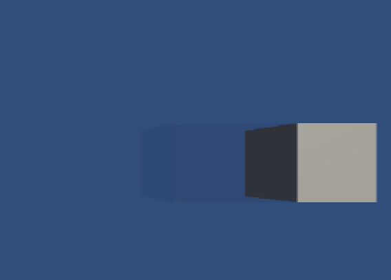
2.深度和法线纹理
1.获取深度和法线纹理
1.原理
深度纹理也是一张渲染纹理,但它存储的是高精度的深度值而不是颜色值。
透视投影:
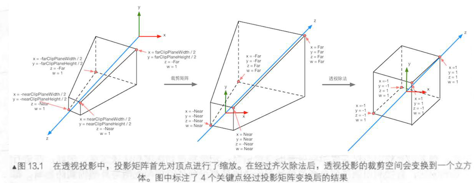
正交投影:
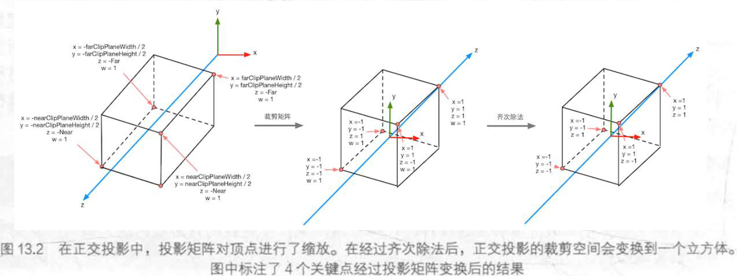
由于NDC的范围在[-1,1],需要映射到[0,1]范围内,我们使用这个公式映射:
$$
d=0.5*z_n+0.5
$$
在 Unity 中,我们可以选择让一个摄像机生成一张深度纹理或是一张深度+法线纹理。
当只生成一张单独的深度纹理时,Unity直接获取深度缓存,使用投射阴影的Pass(LightMode设置为ShadowCaster)来得到深度纹理。
如果生成深度纹理和法线纹理时,Unity 会创建一张和屏幕分辨率相同、精度为 32 位(每个通道为 8 位)的纹理,其中观察空间下的法线信息会被编码进纹理的 R 和 G 通道,而深度信息会被编码进 B 和 A 通道。
2.如何获取深度纹理
直接通过代码访问:
camera.depthTextureMode=DepthTextureMode.Depth;设置好摄像机后,我们就可以在Shader通过声明_CameraDepthTexture_变量来访问。
纹理采样得到深度值后,得到的深度值往往是非线性的。通过下列公式转化成线性:
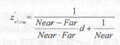
这个公式的取值范围是[Near,Far],转换到[0,1]是这个公式:
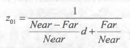
Unity也提供了两个内置函数来进行上式的计算:_LinearEyeDepth_(对应第一个公式)和_Linear01Depth_(对应第二个公式),
2.使用深度纹理模拟运动模糊
刚刚使用了多张屏幕图像来模拟运动模糊的效果。另一种办法是使用速度映射图。我们可以用深度纹理在片元着色器中为每个像素计算其在世界空间下的位置,这是通过使用当前的视角*投影矩阵的逆矩阵对 NDC 下的顶点坐标进行变换得到的。然后使用前 一 帧的视角*投影矩阵对其进行变换, 得到该位置在前一帧中的 NDC 坐标。然后,我们计算前 一 帧和当前帧的位置差,生成该像素的速度。
cs代码:
using System;
using System.Collections;
using System.Collections.Generic;
using System.Net.NetworkInformation;
using Unity.VisualScripting;
using UnityEngine;

public class MotionBlurWithDepthTexture : PostEffectsBase
{
    public Shader motionBlurShader;
    private Material motionBlurMaterial=null;

    public Material material
    {
        get
        {
            motionBlurMaterial = CheckShaderAndCreateMaterial(motionBlurShader, motionBlurMaterial);
            return motionBlurMaterial;
        }
    }

    [Range(0.0f, 1.0f)] public float blurSize = 0.5f;
    private Camera myCamera;

    public Camera camera
    {
        get
        {
            myCamera = GetComponent<Camera>();
            return myCamera;
        }
    }

    private Matrix4x4 previousViewProjectionMatrix;
    //保存上一帧摄像机的视角*投影矩阵
    private void OnEnable()
    {
        camera.depthTextureMode |= DepthTextureMode.Depth;

    }

    private void OnRenderImage(RenderTexture src, RenderTexture dest)
    {
        if (material!=null)
        {

            material.SetFloat("_BlurSize",blurSize);
            material.SetMatrix("_PreviousViewProjectionMatrix",previousViewProjectionMatrix);
            Matrix4x4 currentViewProMat = camera.projectionMatrix * camera.worldToCameraMatrix;
            Matrix4x4 currentViewInvMat = currentViewProMat.inverse;
            material.SetMatrix("_CurrentViewProjectionInverseMatrix",currentViewInvMat);
            previousViewProjectionMatrix = currentViewProMat;
            Graphics.Blit(src,dest,material);

        }
        else
        {
            Graphics.Blit(src,dest);
        }
    }
}
Shader代码:
Shader "Unity Shader Books/Chapter 13/Motion Blur With Depth Texture"
{
    Properties {
		_MainTex ("Base (RGB)", 2D) = "white" {}
		_BlurSize ("Blur Size", Float) = 1.0
	}
	SubShader {
		CGINCLUDE

		#include "UnityCG.cginc"

		sampler2D _MainTex;
		half4 _MainTex_TexelSize;
		sampler2D _CameraDepthTexture;
		float4x4 _CurrentViewProjectionInverseMatrix;
		float4x4 _PreviousViewProjectionMatrix;
		half _BlurSize;

		struct v2f {
			float4 pos : SV_POSITION;
			half2 uv : TEXCOORD0;
			half2 uv_depth : TEXCOORD1;
		};

		v2f vert(appdata_img v) {
			v2f o;
			o.pos = UnityObjectToClipPos(v.vertex);

			o.uv = v.texcoord;
			o.uv_depth = v.texcoord;

			#if UNITY_UV_STARTS_AT_TOP
			if (_MainTex_TexelSize.y < 0)
				o.uv_depth.y = 1 - o.uv_depth.y;
			#endif

			return o;
		}

		fixed4 frag(v2f i) : SV_Target {
			// Get the depth buffer value at this pixel.
			float d = SAMPLE_DEPTH_TEXTURE(_CameraDepthTexture, i.uv_depth);
			// H is the viewport position at this pixel in the range -1 to 1.
			float4 H = float4(i.uv.x * 2 - 1, i.uv.y * 2 - 1, d * 2 - 1, 1);
			// Transform by the view-projection inverse.
			float4 D = mul(_CurrentViewProjectionInverseMatrix, H);
			// Divide by w to get the world position.
			float4 worldPos = D / D.w;

			// Current viewport position
			float4 currentPos = H;
			// Use the world position, and transform by the previous view-projection matrix.
			float4 previousPos = mul(_PreviousViewProjectionMatrix, worldPos);
			// Convert to nonhomogeneous points [-1,1] by dividing by w.
			previousPos /= previousPos.w;

			// Use this frame's position and last frame's to compute the pixel velocity.
			float2 velocity = (currentPos.xy - previousPos.xy)/2.0f;

			float2 uv = i.uv;
			float4 c = tex2D(_MainTex, uv);
			uv += velocity * _BlurSize;
			for (int it = 1; it < 3; it++, uv += velocity * _BlurSize) {
				float4 currentColor = tex2D(_MainTex, uv);
				c += currentColor;
			}
			c /= 3;

			return fixed4(c.rgb, 1.0);
		}

		ENDCG

		Pass {
			ZTest Always Cull Off ZWrite Off

			CGPROGRAM

			#pragma vertex vert
			#pragma fragment frag

			ENDCG
		}
	}
	FallBack Off
}
3.全局雾效
基于屏幕后处理的全局雾效的关键是, 根据深度纹理来重建每个像素在世界空间下的位置。
1.重建世界坐标
只需要知道摄像机在世界空间下的位置 ,以及世界空间下该像素相对于摄像机的偏移量,把它们相加就可以得到该像素的世界坐标。
float4 worldPos=_WorldSpaceCameraPos+LinearDepth*interpolatedRay;interpolatedRay 来源于对近裁剪平面的 4 个角的某个特定向量的插值,这 4 个向 量包含 了它们到摄像机的方向和距离信息,我们可以利用摄像机的近裁剪平面距离、 FOV 、横纵比计算而得。
$$
halfHeight=Near*tan(FOV/2)
$$
$$
toTop=camera.up*halfHeight
$$
$$
toRight=camera.right*halfHeight.aspect
$$
得到辅助向量后,就可以计算四个角相对于摄像机的方向了。
以左上角为例:
$$
TL=camera.forward*Near+toTop-toRight
$$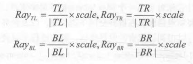
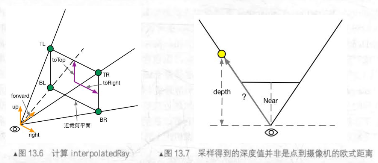
2.雾的计算
在简单的雾效实现中,我们需要计算一个雾效系数f, 作为混合原始颜色和雾的颜色的混合系数:
float3 afterFog=f*fogColor+(1-f)*origColor;在 Unity 内置的雾效实现中,支待三种雾的计算方式–线性 (Linear) 、指数 (Exponential) 以及指数的平方 (Exponential Squared )
计算公式如下:

3.实践
cs代码如下:
using System;
using System.Collections;
using System.Collections.Generic;
using UnityEngine;

public class FogWithDepthTexture : PostEffectsBase
{
    public Shader fogShader;
    private Material fogMaterial=null;

    public Material material
    {
        get
        {
            fogMaterial = CheckShaderAndCreateMaterial(fogShader, fogMaterial);
            return fogMaterial;
        }
    }

    private Camera myCamera;

    public Camera camera
    {
        get
        {
            myCamera = GetComponent<Camera>();
            return myCamera;

        }
    }

    private Transform myCameraTransform;

    public Transform cameraTransform
    {
        get
        {
            myCameraTransform = camera.transform;
            return myCameraTransform;
        }
    }

    [Range(0.0f, 3.0f)] public float fogDensity = 1.0f;
    public Color fogColor = Color.red;
    public float fogStart = 0.0f;
    public float fogEnd = 2.0f;

    private void OnEnable()
    {
        camera.depthTextureMode |= DepthTextureMode.Depth;

    }

    private void OnRenderImage(RenderTexture src, RenderTexture dest)
    {
        if (material!=null)
        {
            Matrix4x4 frustumCorners=Matrix4x4.identity;
            float fov = camera.fieldOfView;
            float near = camera.nearClipPlane;
            float far = camera.farClipPlane;
            float aspect = camera.aspect;

            float halfHeight =near* Mathf . Tan(fov * 0.5f * Mathf.Deg2Rad);

            Vector3 toRight = cameraTransform.right * halfHeight * aspect;
            Vector3 toTop = cameraTransform.up * halfHeight ;
            Vector3 topLeft = cameraTransform.forward *near+ toTop - toRight;
            float scale= topLeft.magnitude / near;
            topLeft . Normalize();
            topLeft *= scale;
            Vector3 topRight= cameraTransform.forward*near+ toRight + toTop ;
            topRight.Normalize();
            topRight *= scale ;
            Vector3 bottomLeft = cameraTransform . forward * near - toTop - toRight;
            bottomLeft.Normalize();
            bottomLeft *= scale;
            Vector3 bottomRight = cameraTransform . forward *near+ toRight - toTop;
            bottomRight . Normalize();
            bottomRight *= scale ;
            frustumCorners.SetRow(0 , bottomLeft) ;
            frustumCorners . SetRow(1, bottomRight);
            frustumCorners . SetRow(2, topRight);
            frustumCorners . SetRow(3, topLeft) ;
            material.SetMatrix("_FrustumCornersRay", frustumCorners);
            material.SetMatrix( "_ViewProjectionInverseMatrix",
                (camera .projectionMatrix * camera . worldToCameraMatrix).inverse);
            material.SetFloat ( " _FogDensity ", fogDensity );
            material . SetColor( " _FogColor ", fogColor);
            material.SetFloat( " _FogStart ", fogStart);
            material.SetFloat ( " _FogEnd ", fogEnd) ;
            Graphics.Blit(src , dest, material);
        }
        else
        {
            Graphics.Blit(src,dest);
        }
    }
}
Shader代码:
Shader "Unity Shader Books/Chapter 13/Fog With Depth Texture"
{
    Properties {
		_MainTex ("Base (RGB)", 2D) = "white" {}
		_FogDensity ("Fog Density", Float) = 1.0
		_FogColor ("Fog Color", Color) = (1, 1, 1, 1)
		_FogStart ("Fog Start", Float) = 0.0
		_FogEnd ("Fog End", Float) = 1.0
	}
	SubShader {
		CGINCLUDE

		#include "UnityCG.cginc"

		float4x4 _FrustumCornersRay;

		sampler2D _MainTex;
		half4 _MainTex_TexelSize;
		sampler2D _CameraDepthTexture;
		half _FogDensity;
		fixed4 _FogColor;
		float _FogStart;
		float _FogEnd;

		struct v2f {
			float4 pos : SV_POSITION;
			half2 uv : TEXCOORD0;
			half2 uv_depth : TEXCOORD1;
			float4 interpolatedRay : TEXCOORD2;
		};

		v2f vert(appdata_img v) {
			v2f o;
			o.pos = UnityObjectToClipPos(v.vertex);

			o.uv = v.texcoord;
			o.uv_depth = v.texcoord;

			#if UNITY_UV_STARTS_AT_TOP
			if (_MainTex_TexelSize.y < 0)
				o.uv_depth.y = 1 - o.uv_depth.y;
			#endif

			int index = 0;
			if (v.texcoord.x < 0.5 && v.texcoord.y < 0.5) {
				index = 0;
			} else if (v.texcoord.x > 0.5 && v.texcoord.y < 0.5) {
				index = 1;
			} else if (v.texcoord.x > 0.5 && v.texcoord.y > 0.5) {
				index = 2;
			} else {
				index = 3;
			}

			#if UNITY_UV_STARTS_AT_TOP
			if (_MainTex_TexelSize.y < 0)
				index = 3 - index;
			#endif

			o.interpolatedRay = _FrustumCornersRay[index];

			return o;
		}

		fixed4 frag(v2f i) : SV_Target {
			float linearDepth = LinearEyeDepth(SAMPLE_DEPTH_TEXTURE(_CameraDepthTexture, i.uv_depth));
			float3 worldPos = _WorldSpaceCameraPos + linearDepth * i.interpolatedRay.xyz;

			float fogDensity = (_FogEnd - worldPos.y) / (_FogEnd - _FogStart);
			fogDensity = saturate(fogDensity * _FogDensity);

			fixed4 finalColor = tex2D(_MainTex, i.uv);
			finalColor.rgb = lerp(finalColor.rgb, _FogColor.rgb, fogDensity);

			return finalColor;
		}

		ENDCG

		Pass {
			ZTest Always Cull Off ZWrite Off

			CGPROGRAM

			#pragma vertex vert
			#pragma fragment frag

			ENDCG
		}
	}
	FallBack Off
}
效果图:
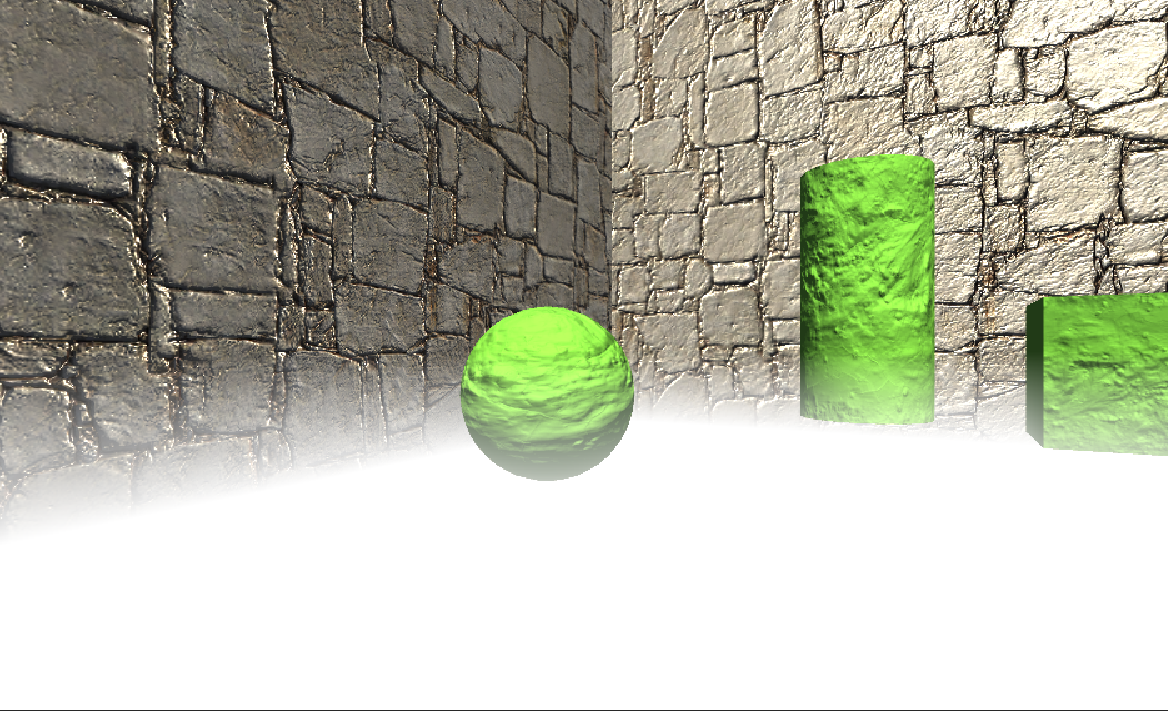
4.使用深度和法线纹理描边
前面提到了如何使用Sobel算子对屏幕进行边缘检测,实现描边效果。但这种直接利用颜色信息进行边缘检测的方法会产生很多我们不希望得到的边缘线(物体纹理,阴影的位置也被描上黑边)。
这里我们使用Roberts算子:计算左上角和右下角的差值,乘以右上角和左下角的差值,作为评估边缘的依据。
cs代码:
using UnityEngine;
using System.Collections;

public class EdgeDetectNormalsAndDepth : PostEffectsBase {

    public Shader edgeDetectShader;
    private Material edgeDetectMaterial = null;
    public Material material {
        get {
            edgeDetectMaterial = CheckShaderAndCreateMaterial(edgeDetectShader, edgeDetectMaterial);
            return edgeDetectMaterial;
        }
    }

    [Range(0.0f, 1.0f)]
    public float edgesOnly = 0.0f;

    public Color edgeColor = Color.black;

    public Color backgroundColor = Color.white;

    public float sampleDistance = 1.0f;
    //使用的采样距离

    public float sensitivityDepth = 1.0f;

    public float sensitivityNormals = 1.0f;
    //可以认为是灵敏度

    void OnEnable() {
        GetComponent<Camera>().depthTextureMode |= DepthTextureMode.DepthNormals;
    }

    [ImageEffectOpaque]
    void OnRenderImage (RenderTexture src, RenderTexture dest) {
        if (material != null)
        {
            material.SetFloat("_EdgeOnly", edgesOnly);
            material.SetColor("_EdgeColor", edgeColor);
            material.SetColor("_BackgroundColor", backgroundColor);
            material.SetFloat("_SampleDistance", sampleDistance);
            material.SetVector("_Sensitivity", new Vector4(sensitivityNormals, sensitivityDepth, 0.0f, 0.0f));

            Graphics.Blit(src, dest, material);
        }
        else
        {
            Graphics.Blit(src, dest);
        }
    }
}
Shader代码:
// Upgrade NOTE: replaced 'mul(UNITY_MATRIX_MVP,*)' with 'UnityObjectToClipPos(*)'

Shader "Unity Shader Books/Chapter 13/Edge Detection Normals And Depth" {
	Properties {
		_MainTex ("Base (RGB)", 2D) = "white" {}
		_EdgeOnly ("Edge Only", Float) = 1.0
		_EdgeColor ("Edge Color", Color) = (0, 0, 0, 1)
		_BackgroundColor ("Background Color", Color) = (1, 1, 1, 1)
		_SampleDistance ("Sample Distance", Float) = 1.0
		_Sensitivity ("Sensitivity", Vector) = (1, 1, 1, 1)
	}
	SubShader {
		CGINCLUDE

		#include "UnityCG.cginc"

		sampler2D _MainTex;
		half4 _MainTex_TexelSize;
		fixed _EdgeOnly;
		fixed4 _EdgeColor;
		fixed4 _BackgroundColor;
		float _SampleDistance;
		half4 _Sensitivity;

		sampler2D _CameraDepthNormalsTexture;

		struct v2f {
			float4 pos : SV_POSITION;
			half2 uv[5]: TEXCOORD0;
		};

		v2f vert(appdata_img v) {
			v2f o;
			o.pos = UnityObjectToClipPos(v.vertex);

			half2 uv = v.texcoord;
			o.uv[0] = uv;

			#if UNITY_UV_STARTS_AT_TOP
			if (_MainTex_TexelSize.y < 0)
				uv.y = 1 - uv.y;
			#endif

			o.uv[1] = uv + _MainTex_TexelSize.xy * half2(1,1) * _SampleDistance;
			o.uv[2] = uv + _MainTex_TexelSize.xy * half2(-1,-1) * _SampleDistance;
			o.uv[3] = uv + _MainTex_TexelSize.xy * half2(-1,1) * _SampleDistance;
			o.uv[4] = uv + _MainTex_TexelSize.xy * half2(1,-1) * _SampleDistance;

			return o;
		}

		half CheckSame(half4 center, half4 sample) {
			half2 centerNormal = center.xy;
			float centerDepth = DecodeFloatRG(center.zw);
			half2 sampleNormal = sample.xy;
			float sampleDepth = DecodeFloatRG(sample.zw);

			// difference in normals
			// do not bother decoding normals - there's no need here
			half2 diffNormal = abs(centerNormal - sampleNormal) * _Sensitivity.x;
			int isSameNormal = (diffNormal.x + diffNormal.y) < 0.1;
			// difference in depth
			float diffDepth = abs(centerDepth - sampleDepth) * _Sensitivity.y;
			// scale the required threshold by the distance
			int isSameDepth = diffDepth < 0.1 * centerDepth;

			// return:
			// 1 - if normals and depth are similar enough
			// 0 - otherwise
			return isSameNormal * isSameDepth ? 1.0 : 0.0;
		}

		fixed4 fragRobertsCrossDepthAndNormal(v2f i) : SV_Target {
			half4 sample1 = tex2D(_CameraDepthNormalsTexture, i.uv[1]);
			half4 sample2 = tex2D(_CameraDepthNormalsTexture, i.uv[2]);
			half4 sample3 = tex2D(_CameraDepthNormalsTexture, i.uv[3]);
			half4 sample4 = tex2D(_CameraDepthNormalsTexture, i.uv[4]);

			half edge = 1.0;

			edge *= CheckSame(sample1, sample2);
			edge *= CheckSame(sample3, sample4);

			fixed4 withEdgeColor = lerp(_EdgeColor, tex2D(_MainTex, i.uv[0]), edge);
			fixed4 onlyEdgeColor = lerp(_EdgeColor, _BackgroundColor, edge);

			return lerp(withEdgeColor, onlyEdgeColor, _EdgeOnly);
		}

		ENDCG

		Pass {
			ZTest Always Cull Off ZWrite Off

			CGPROGRAM

			#pragma vertex vert
			#pragma fragment fragRobertsCrossDepthAndNormal

			ENDCG
		}
	}
	FallBack Off
}
效果图:
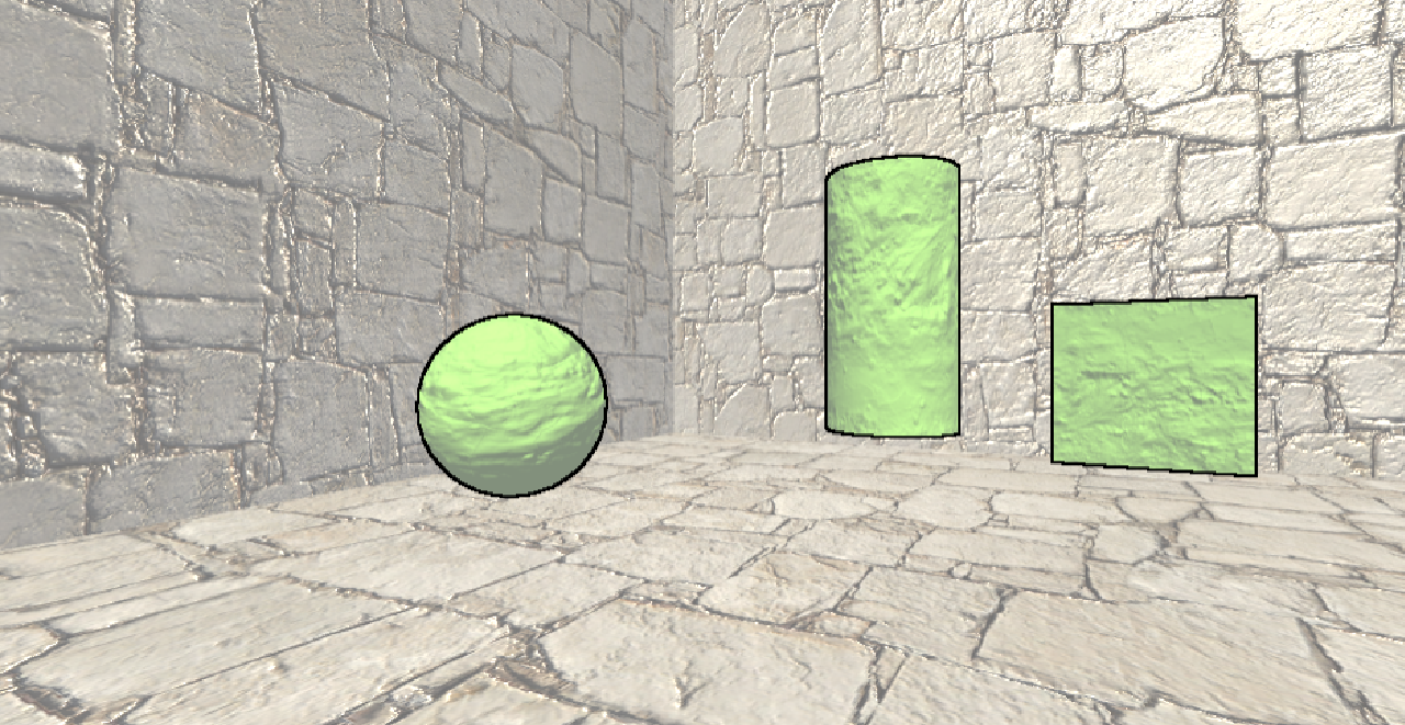
3.卡通渲染
1.卡通风格的渲染
1.绘制轮廓线
这种方法大概有五种类型:
• 基于观察角度和表面法线的轮廓线渲染。这种方法使用视角方向和表面法线的点乘结果来得到轮廓线的信息。这种方法简单快速,可以在 一个 Pass 中就得到渲染结果,但局限性很大, 很多模型渲染出来的描边效果都不尽如人意。
• 过程式几何轮廓线渲染。这种方法的核心是使用两个 Pass 渲染。第 一 个 Pass渲染背面的面片,并使用某些技术让它的轮廓可见;第二个 Pass 再正常渲染正面的面片。这种方法的优点在于快速有效,并且适用于绝大多数表面平滑的模型,但它的缺点是不适合类似于立方体这样平整的模型。
• 基于图像处理的轮廓线渲染。我们在第 12 、 13 章介绍的边缘检测的方法就属于这个类别。这种方法的优点在于, 可以适用于任何种类的模型。但它也有自身的局限所在 ,一些深度和法线变化很小的轮廓无法被检测出来,例如桌子上的纸张。
• 基于轮廓边检测的轮廓线渲染。上面提到的各种方法,一个最大的问题是,无法控制轮廓线的风格渲染。对于一些情况,我们希望可以渲染出独特风格的轮廓线,例如水墨风格等。为此,我们希望可以检测出精确的轮廓边,然后直接渲染它们。检测 一 条边是否是轮廓边的公式很简单,我们只需要检查和这条边相邻的两个三角面片是否满足以下条件:

n0和n1表示两个相邻三角面的法向。v是从视角到该边上任意顶点的方向。这个公式的本质就是检查两个相邻三角面片是否一个朝正面,一个朝背面。
• 最后 一 个种类就是混合了上述的几种渲染方法。例如 , 首先找到精确的轮廓边,把模型和轮廓边渲染到纹理中,再使用图像处理的方法识别出轮廓线,并在图像空间下进行风格化渲染。
2.添加高光
我们计算normal和halfDir的点乘结果,然后与阈值比较,如果小于阈值,则高光反射系数为0.否则为1
float spec=dot(worldNormal,worldHalfDir);
spec=lerp(0,1,smoothstep(-w,w,spec-threshold));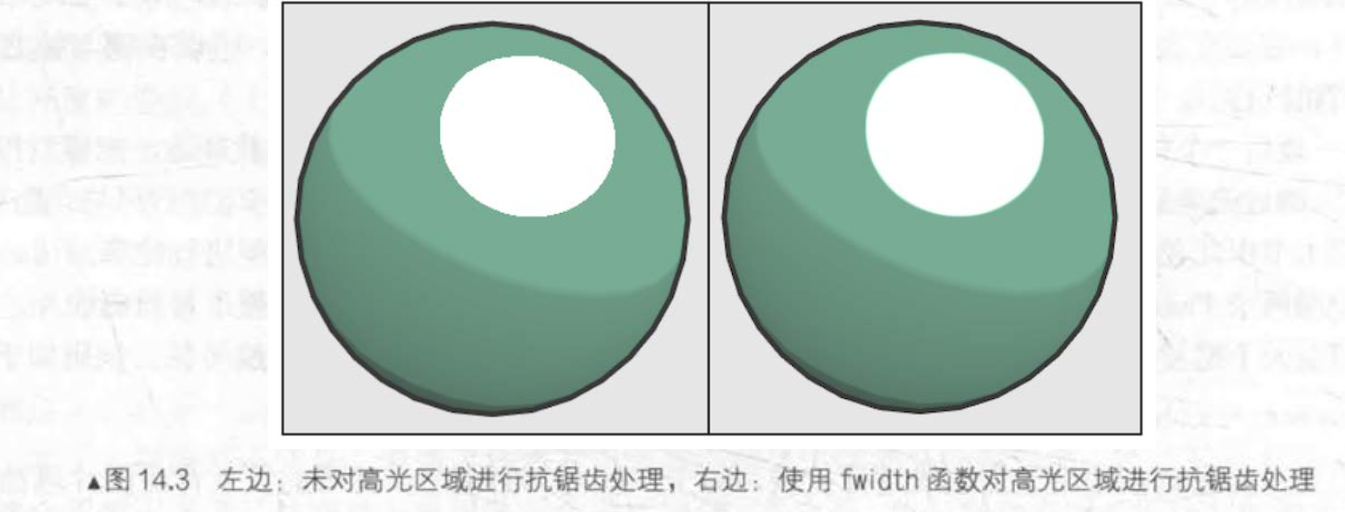
3.实践
Shader代码:
Shader "Unity Shader Books/Chapter 14/Toon Shading"
{
    Properties
    {
        _Color ("Color Tint", Color) = (1,1,1,1)
        _MainTex ("Main Tex", 2D) = "white" {}
        _Ramp("Ramp Texture",2D)="white"{}
        //控制漫反射色调的渐变纹理
        _Outline("Outline",Range(0,1))=0.1
        //控制轮廓线宽度
        _OutlineColor("Outline Color",Color)=(0,0,0,1)
        //控制轮廓线颜色
        _Specular("Specular",Color)=(1,1,1,1)
        _SpecularColor("Specular Scale",Range(0,0.1))=0.01
    }
    SubShader {
		Tags { "RenderType"="Opaque" "Queue"="Geometry"}

		Pass {
			NAME "OUTLINE"

			Cull Front

			CGPROGRAM

			#pragma vertex vert
			#pragma fragment frag

			#include "UnityCG.cginc"

			float _Outline;
			fixed4 _OutlineColor;

			struct a2v {
				float4 vertex : POSITION;
				float3 normal : NORMAL;
			};

			struct v2f {
			    float4 pos : SV_POSITION;
			};

			v2f vert (a2v v) {
				v2f o;

				float4 pos = mul(UNITY_MATRIX_MV, v.vertex);
				float3 normal = mul((float3x3)UNITY_MATRIX_IT_MV, v.normal);
				normal.z = -0.5;
				pos = pos + float4(normalize(normal), 0) * _Outline;
				o.pos = mul(UNITY_MATRIX_P, pos);

				return o;
			}

			float4 frag(v2f i) : SV_Target {
				return float4(_OutlineColor.rgb, 1);
			}
			//描边需要的顶点着色器和片元着色器

			ENDCG
		}

		Pass {
			Tags { "LightMode"="ForwardBase" }

			Cull Back

			CGPROGRAM

			#pragma vertex vert
			#pragma fragment frag

			#pragma multi_compile_fwdbase

			#include "UnityCG.cginc"
			#include "Lighting.cginc"
			#include "AutoLight.cginc"
			#include "UnityShaderVariables.cginc"

			fixed4 _Color;
			sampler2D _MainTex;
			float4 _MainTex_ST;
			sampler2D _Ramp;
			fixed4 _Specular;
			fixed _SpecularScale;

			struct a2v {
				float4 vertex : POSITION;
				float3 normal : NORMAL;
				float4 texcoord : TEXCOORD0;
				float4 tangent : TANGENT;
			};

			struct v2f {
				float4 pos : POSITION;
				float2 uv : TEXCOORD0;
				float3 worldNormal : TEXCOORD1;
				float3 worldPos : TEXCOORD2;
				SHADOW_COORDS(3)
			};

			v2f vert (a2v v) {
				v2f o;

				o.pos = UnityObjectToClipPos( v.vertex);
				o.uv = TRANSFORM_TEX (v.texcoord, _MainTex);
				o.worldNormal  = UnityObjectToWorldNormal(v.normal);
				o.worldPos = mul(unity_ObjectToWorld, v.vertex).xyz;

				TRANSFER_SHADOW(o);

				return o;
			}

			float4 frag(v2f i) : SV_Target {
				fixed3 worldNormal = normalize(i.worldNormal);
				fixed3 worldLightDir = normalize(UnityWorldSpaceLightDir(i.worldPos));
				fixed3 worldViewDir = normalize(UnityWorldSpaceViewDir(i.worldPos));
				fixed3 worldHalfDir = normalize(worldLightDir + worldViewDir);

				fixed4 c = tex2D (_MainTex, i.uv);
				fixed3 albedo = c.rgb * _Color.rgb;

				fixed3 ambient = UNITY_LIGHTMODEL_AMBIENT.xyz * albedo;

				UNITY_LIGHT_ATTENUATION(atten, i, i.worldPos);

				fixed diff =  dot(worldNormal, worldLightDir);
				diff = (diff * 0.5 + 0.5) * atten;

				fixed3 diffuse = _LightColor0.rgb * albedo * tex2D(_Ramp, float2(diff, diff)).rgb;

				fixed spec = dot(worldNormal, worldHalfDir);
				fixed w = fwidth(spec) * 2.0;
				fixed3 specular = _Specular.rgb * lerp(0, 1, smoothstep(-w, w, spec + _SpecularScale - 1)) * step(0.0001, _SpecularScale);

				return fixed4(ambient + diffuse + specular, 1.0);
			}

			ENDCG
		}
    }
    FallBack "Diffuse"
}
效果图:
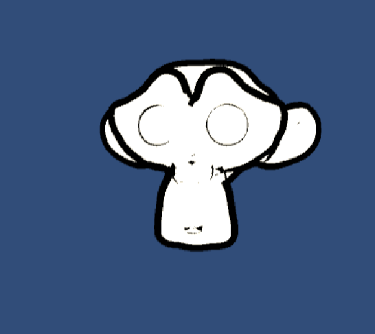
2.素描风格的渲染:
Shader "Unity Shader Books/Chapter 14/Hatching"
{
	Properties
	{
		_Color ("Color Tint", Color) = (1, 1, 1, 1)
		_TileFactor ("Tile Factor", Float) = 1
		_Outline ("Outline", Range(0, 1)) = 0.1
		_Hatch0 ("Hatch 0", 2D) = "white" {}
		_Hatch1 ("Hatch 1", 2D) = "white" {}
		_Hatch2 ("Hatch 2", 2D) = "white" {}
		_Hatch3 ("Hatch 3", 2D) = "white" {}
		_Hatch4 ("Hatch 4", 2D) = "white" {}
		_Hatch5 ("Hatch 5", 2D) = "white" {}
	}

	SubShader {
		Tags { "RenderType"="Opaque" "Queue"="Geometry"}

		UsePass "Unity Shader Books/Chapter 14/Toon Shading/OUTLINE"

		Pass {
			Tags { "LightMode"="ForwardBase" }

			CGPROGRAM

			#pragma vertex vert
			#pragma fragment frag

			#pragma multi_compile_fwdbase

			#include "UnityCG.cginc"
			#include "Lighting.cginc"
			#include "AutoLight.cginc"
			#include "UnityShaderVariables.cginc"

			fixed4 _Color;
			float _TileFactor;
			sampler2D _Hatch0;
			sampler2D _Hatch1;
			sampler2D _Hatch2;
			sampler2D _Hatch3;
			sampler2D _Hatch4;
			sampler2D _Hatch5;

			struct a2v {
				float4 vertex : POSITION;
				float4 tangent : TANGENT;
				float3 normal : NORMAL;
				float2 texcoord : TEXCOORD0;
			};

			struct v2f {
				float4 pos : SV_POSITION;
				float2 uv : TEXCOORD0;
				fixed3 hatchWeights0 : TEXCOORD1;
				fixed3 hatchWeights1 : TEXCOORD2;
				float3 worldPos : TEXCOORD3;
				SHADOW_COORDS(4)
			};

			v2f vert(a2v v) {
				v2f o;

				o.pos = UnityObjectToClipPos(v.vertex);

				o.uv = v.texcoord.xy * _TileFactor;

				fixed3 worldLightDir = normalize(WorldSpaceLightDir(v.vertex));
				fixed3 worldNormal = UnityObjectToWorldNormal(v.normal);
				fixed diff = max(0, dot(worldLightDir, worldNormal));

				o.hatchWeights0 = fixed3(0, 0, 0);
				o.hatchWeights1 = fixed3(0, 0, 0);

				float hatchFactor = diff * 7.0;

				if (hatchFactor > 6.0) {
					// Pure white, do nothing
				} else if (hatchFactor > 5.0) {
					o.hatchWeights0.x = hatchFactor - 5.0;
				} else if (hatchFactor > 4.0) {
					o.hatchWeights0.x = hatchFactor - 4.0;
					o.hatchWeights0.y = 1.0 - o.hatchWeights0.x;
				} else if (hatchFactor > 3.0) {
					o.hatchWeights0.y = hatchFactor - 3.0;
					o.hatchWeights0.z = 1.0 - o.hatchWeights0.y;
				} else if (hatchFactor > 2.0) {
					o.hatchWeights0.z = hatchFactor - 2.0;
					o.hatchWeights1.x = 1.0 - o.hatchWeights0.z;
				} else if (hatchFactor > 1.0) {
					o.hatchWeights1.x = hatchFactor - 1.0;
					o.hatchWeights1.y = 1.0 - o.hatchWeights1.x;
				} else {
					o.hatchWeights1.y = hatchFactor;
					o.hatchWeights1.z = 1.0 - o.hatchWeights1.y;
				}

				o.worldPos = mul(unity_ObjectToWorld, v.vertex).xyz;

				TRANSFER_SHADOW(o);

				return o;
			}

			fixed4 frag(v2f i) : SV_Target {
				fixed4 hatchTex0 = tex2D(_Hatch0, i.uv) * i.hatchWeights0.x;
				fixed4 hatchTex1 = tex2D(_Hatch1, i.uv) * i.hatchWeights0.y;
				fixed4 hatchTex2 = tex2D(_Hatch2, i.uv) * i.hatchWeights0.z;
				fixed4 hatchTex3 = tex2D(_Hatch3, i.uv) * i.hatchWeights1.x;
				fixed4 hatchTex4 = tex2D(_Hatch4, i.uv) * i.hatchWeights1.y;
				fixed4 hatchTex5 = tex2D(_Hatch5, i.uv) * i.hatchWeights1.z;
				fixed4 whiteColor = fixed4(1, 1, 1, 1) * (1 - i.hatchWeights0.x - i.hatchWeights0.y - i.hatchWeights0.z -
							i.hatchWeights1.x - i.hatchWeights1.y - i.hatchWeights1.z);

				fixed4 hatchColor = hatchTex0 + hatchTex1 + hatchTex2 + hatchTex3 + hatchTex4 + hatchTex5 + whiteColor;

				UNITY_LIGHT_ATTENUATION(atten, i, i.worldPos);

				return fixed4(hatchColor.rgb * _Color.rgb * atten, 1.0);
			}

			ENDCG
		}
	}
	FallBack "Diffuse"
}
效果图:
